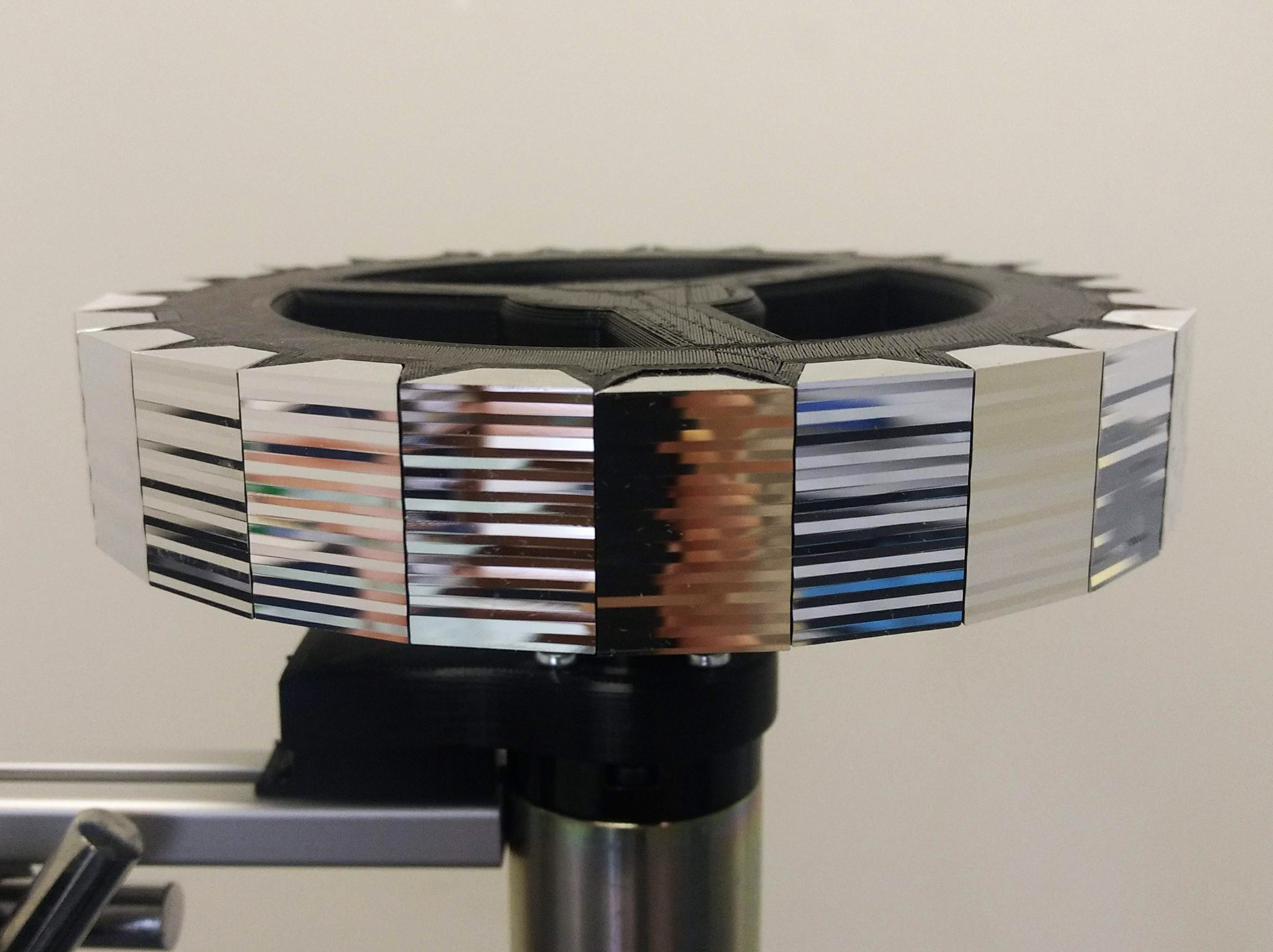
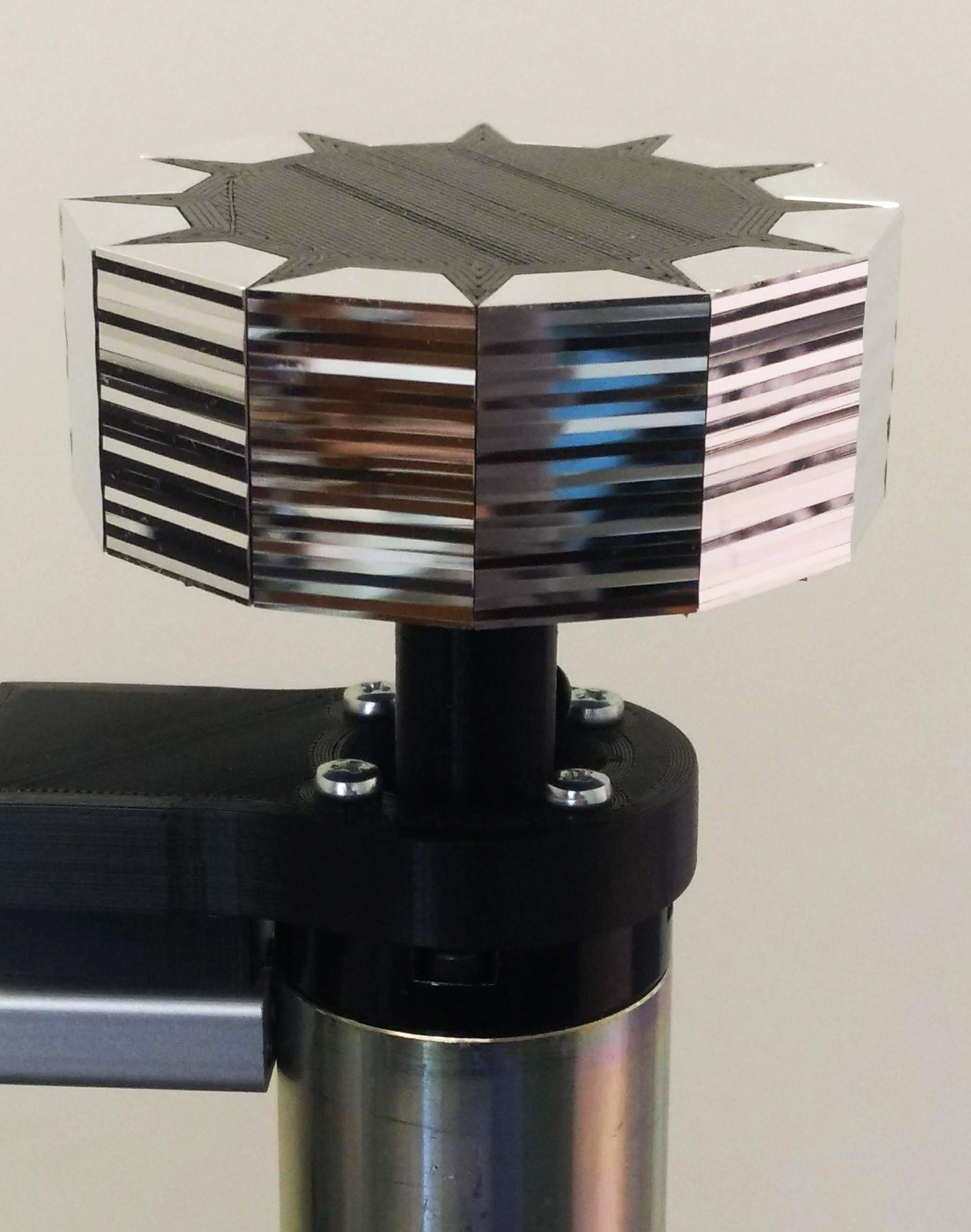
Over the past few weeks I have focused on cutting and polishing facets on the nano-lathe. I first began building a polygon with 6 facets, then I increased this number to 12 and now 24. As mentioned in an earlier post, a greater number of facets decreases the angle of rotation and therefore increases the perceptual illusion of movement in the projected image.
When I created the patterns (cut profiles) for each facet I was interested in having a human element in the pattern, as opposed to an algorithm that generated the cut profiles. Perhaps this desire comes from my background as a hands-on maker. During this residency I have used predominantly digital fabrication (nano-lathe, C ‘n C mill, 3D printers), which primarily use Cartesian axes and g-code. Embedded within this computer/machine code I wanted something ‘hand-made’ or perhaps to be more exact, ‘human-made’! This approach makes different patterns to those produced by a strictly adhered to set of computer rules. Apart from the overall intent and aims of the project, it is important that the actual making of the work has some element of embodied physicality. This adheres to how I use my exposed optical image devices to explore wonder – through physical embodied experience. It is this intersection of art, science and technology that really interests me, the inter-space of old and new, digital and material, tacit and computational, and known and unknown.
To create each cut profile, I used a very rudimentary process of colour coding. This allowed me to visualise the change of depth in each line cut on the same facet and compare this change to previous facet patterns, when deciding on the next line depth. It reminded me of the phrase of ‘painting by numbers’ – in a way, I was trying to humanise the code and subsequently the profile cuts and moving image.
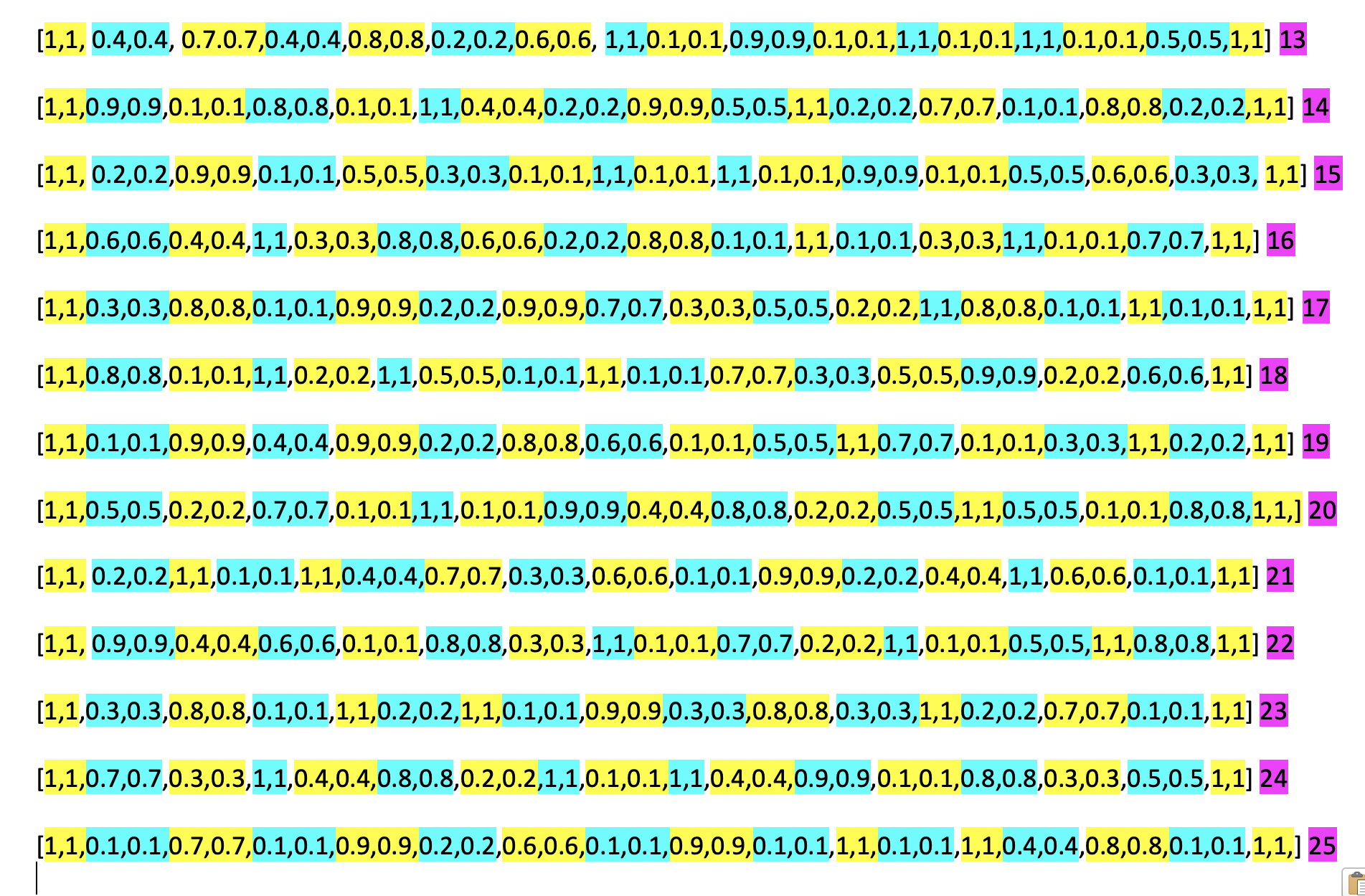
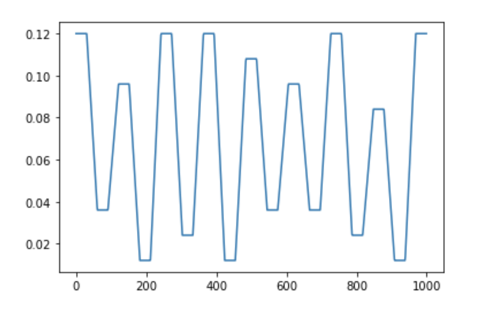
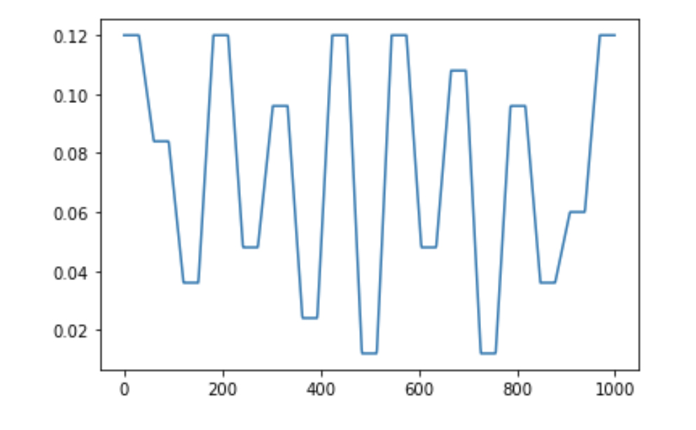
These lines of numbers generated a graph, which visualised the cut paths. This visualisation was part of the Python script that Geoff wrote towards the beginning of the project to translate these numbers into g-code for the nano-lathe to read.
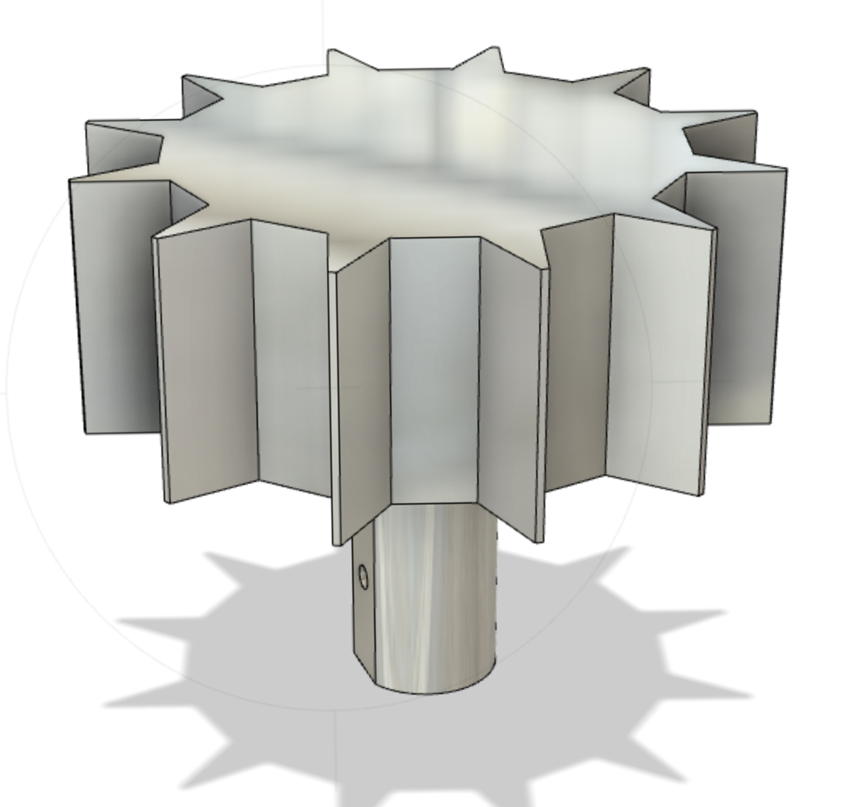
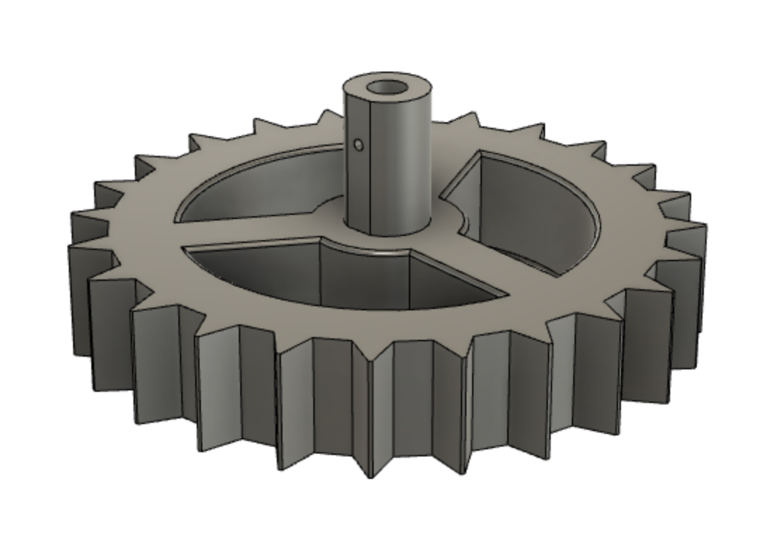
Making the Internal Jigs
I modelled the gigs for the facets in Fusion 360. Before I made the facet blanks using the mill, I tested if it was possible to always use the same facet design no matter how many facets or angle within the polygon. Below are the models I printed which sit inside the mirror facets and connect to the motor shaft. The 24-sided jig was hollowed out to remove some of the weight for the motor. These jigs were printed using PLA filament, but I will now print them using a more precise SLA resin printer.