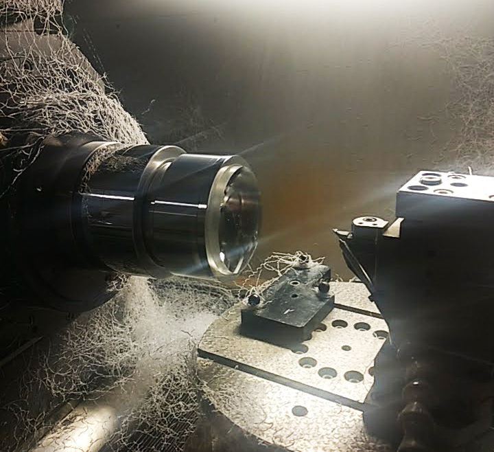
During this week Geoff and myself used the lens blank prepared by Neil Devil to cut a parabolic profile lens. Geoff coded a parabolic curve into the nano-lathe software to generate the .nc file for cutting. We ran a couple of rough passes with the diamond tool to create the curvature of the lens and then optically polished it with a finishing pass. Because we used acrylic, it was much faster than cutting the mirror facets. We completed the top side first and then flipped the lens to cut the other side.
This lens is hopefully the start of our venture into lens making! Geoff and myself are also working with Dr Noelia Martinez Ray to design more accurate curvatures for our lenses. The purpose of this lens is to project an image of the translucent slide so that it focuses just before the surface of the mirror facet.
Translucent image reflected onto the ‘pixelated’ mirror plane.
Both this projected image and the mirror surface are then projected though the objective lens into a combined single image, as per the images I have posted throughout the blog. Below are some images which document the process.
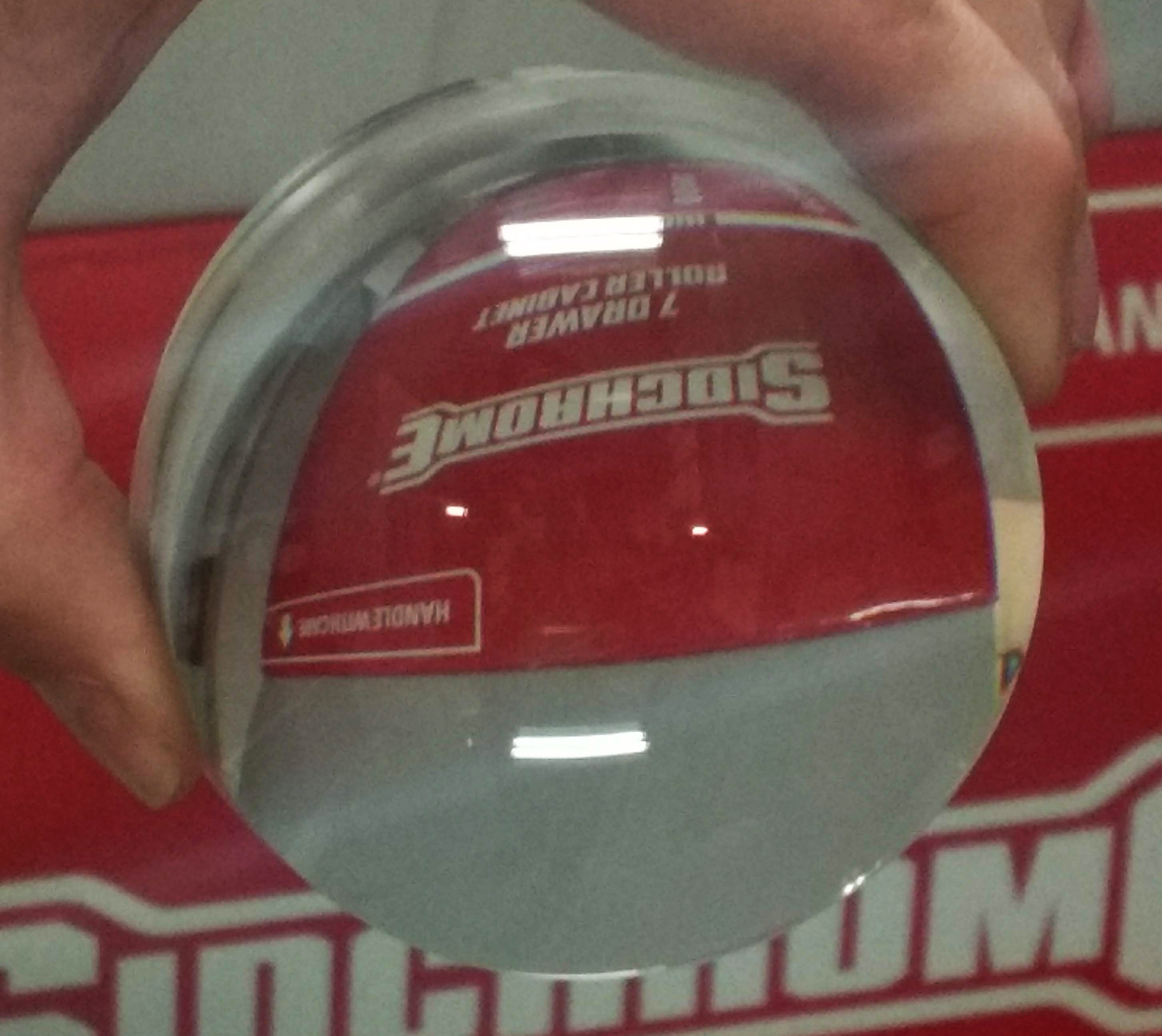
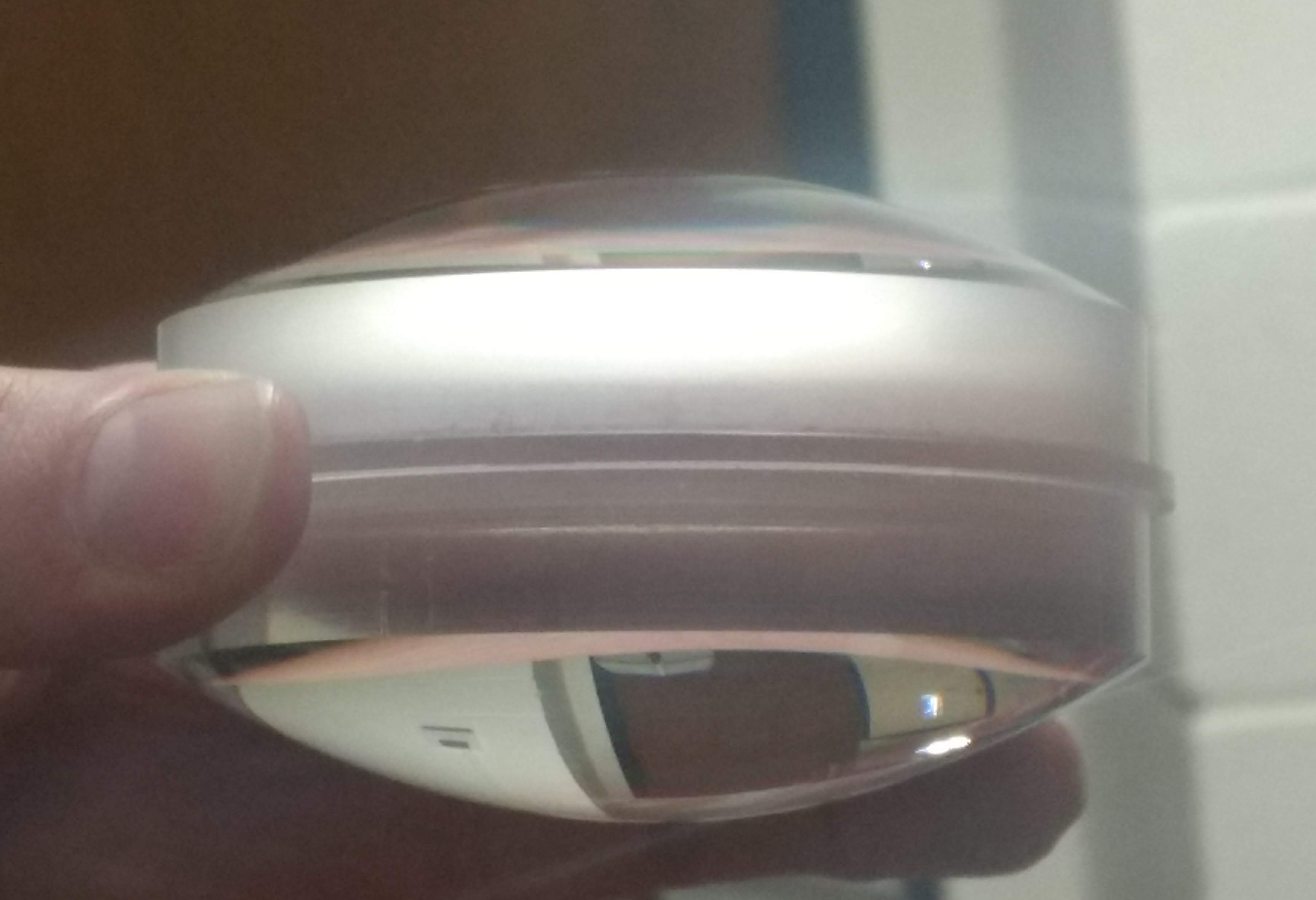
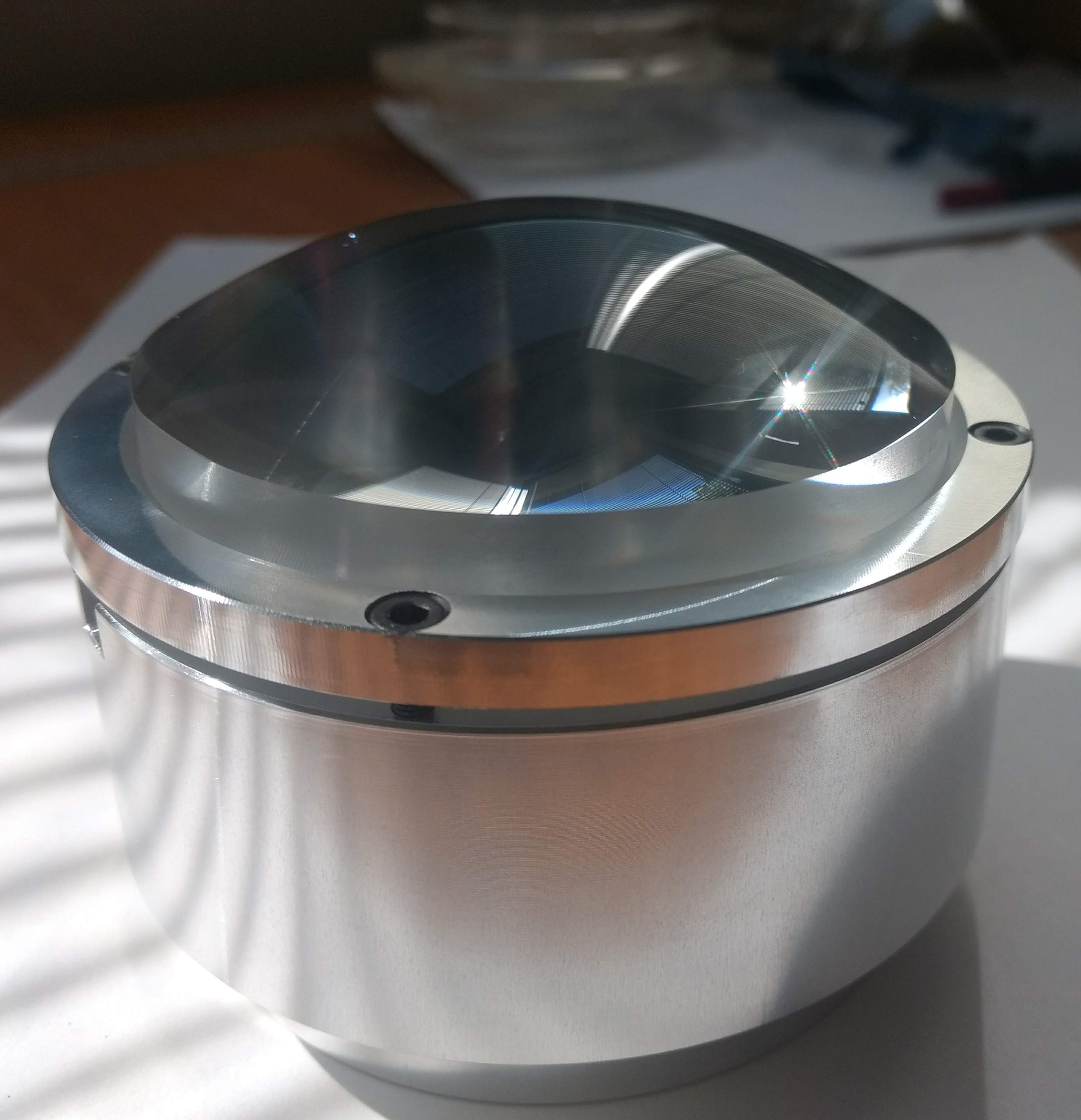
Geoff fixing the flat acrylic disc and jig onto the nano-lathe spindle.The cut and polished lens still attached to the spindle.Optical polished lens.Both sides were cut and polished to crate a bi-convex lens for shorter focal length.Polished lens sitting in the jig.
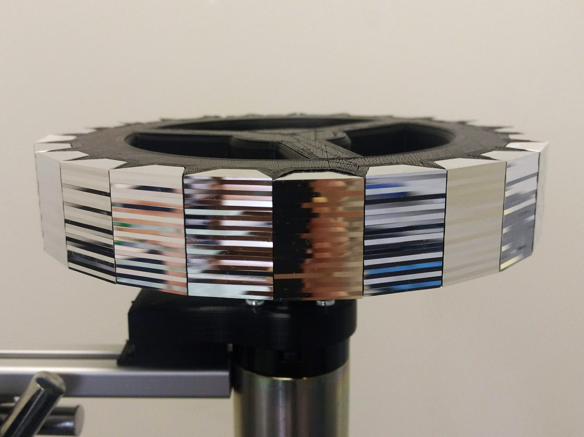
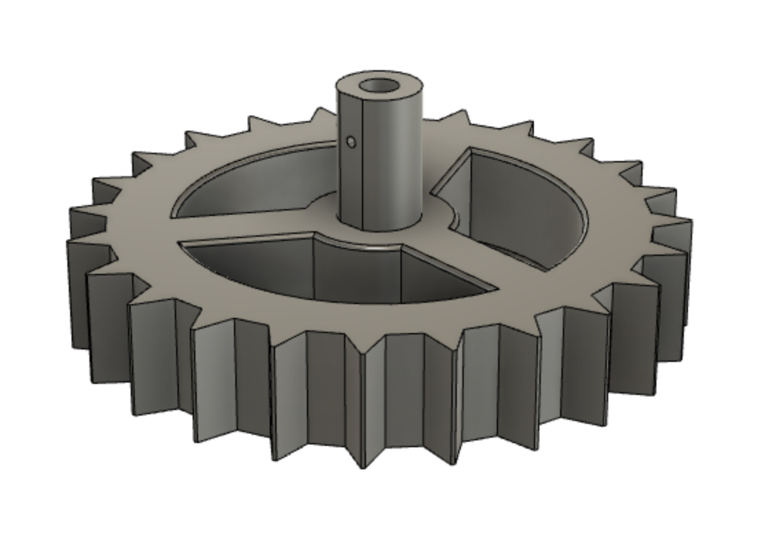
24-sided mirrored polygon. Each facet is cut with a different pattern on the nano-lathe, so that when each facet rotates within the line of the optical system it generates a different image to create the illusion of movement.
Over the past few weeks I have focused on cutting and polishing facets on the nano-lathe. I first began building a polygon with 6 facets, then I increased this number to 12 and now 24. As mentioned in an earlier post, a greater number of facets decreases the angle of rotation and therefore increases the perceptual illusion of movement in the projected image.
When I created the patterns (cut profiles) for each facet I was interested in having a human element in the pattern, as opposed to an algorithm that generated the cut profiles. Perhaps this desire comes from my background as a hands-on maker. During this residency I have used predominantly digital fabrication (nano-lathe, C ‘n C mill, 3D printers), which primarily use Cartesian axes and g-code. Embedded within this computer/machine code I wanted something ‘hand-made’ or perhaps to be more exact, ‘human-made’! This approach makes different patterns to those produced by a strictly adhered to set of computer rules. Apart from the overall intent and aims of the project, it is important that the actual making of the work has some element of embodied physicality. This adheres to how I use my exposed optical image devices to explore wonder – through physical embodied experience. It is this intersection of art, science and technology that really interests me, the inter-space of old and new, digital and material, tacit and computational, and known and unknown.
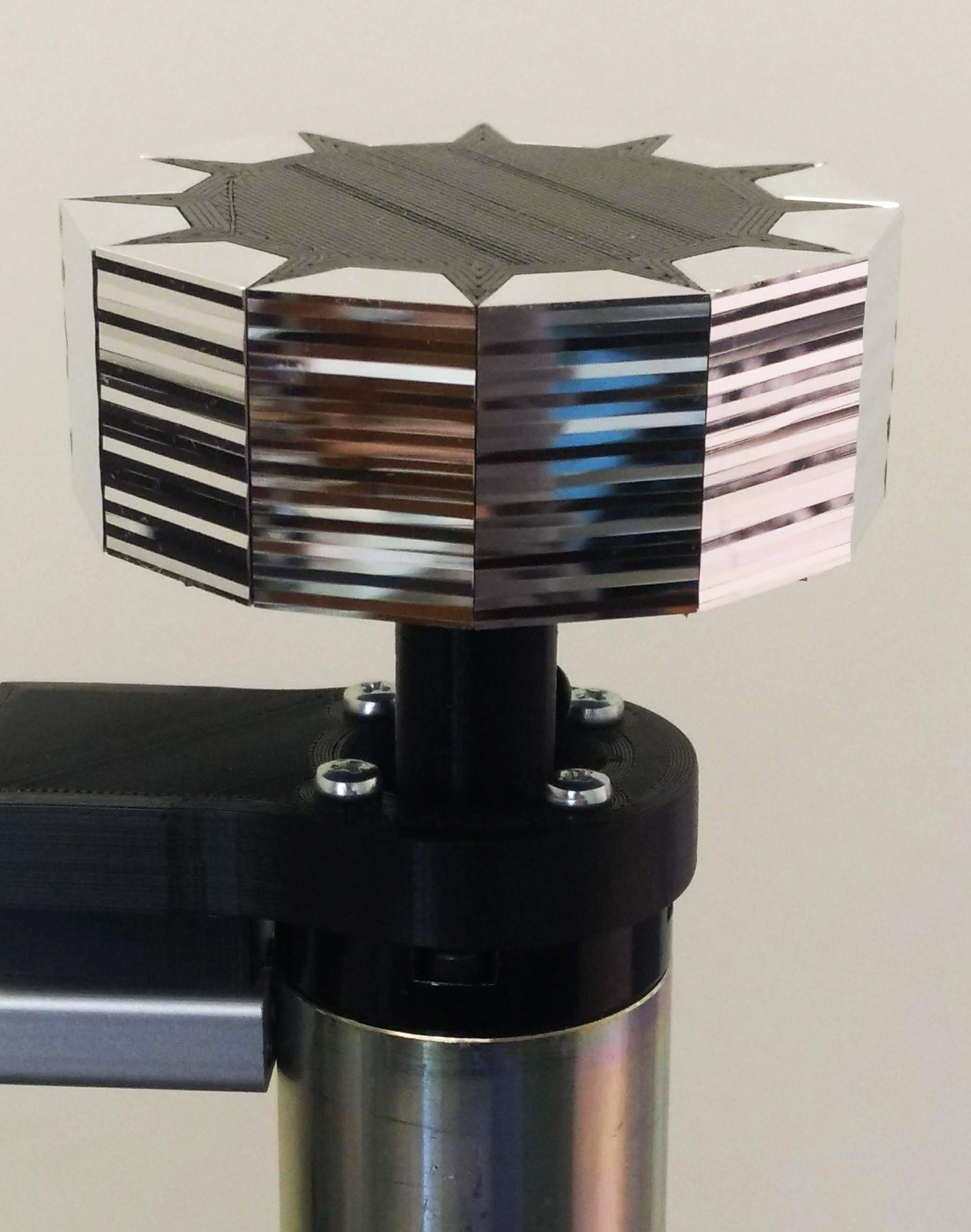
12-sided mirrored polygon
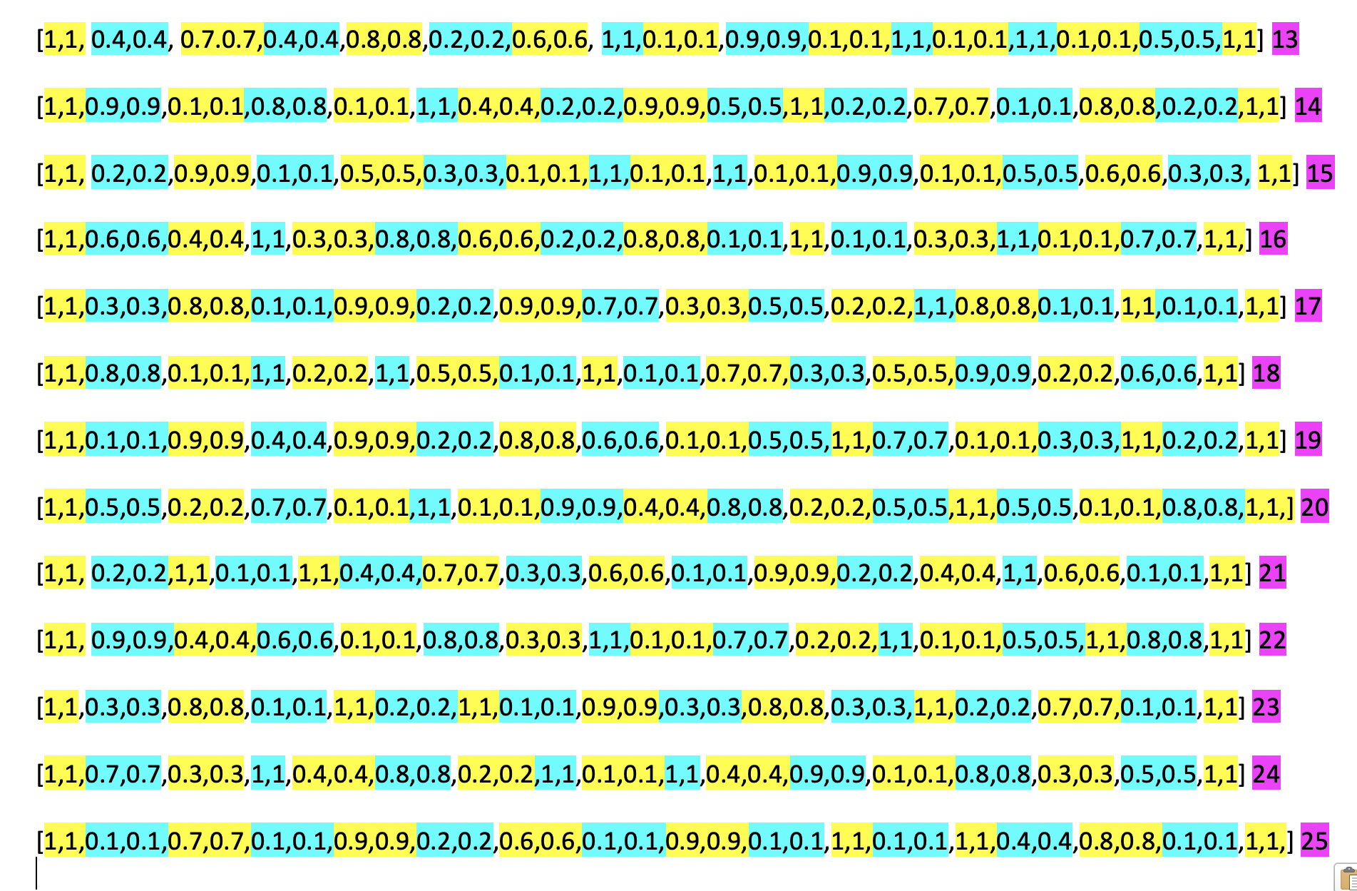
To create each cut profile, I used a very rudimentary process of colour coding. This allowed me to visualise the change of depth in each line cut on the same facet and compare this change to previous facet patterns, when deciding on the next line depth. It reminded me of the phrase of ‘painting by numbers’ – in a way, I was trying to humanise the code and subsequently the profile cuts and moving image.
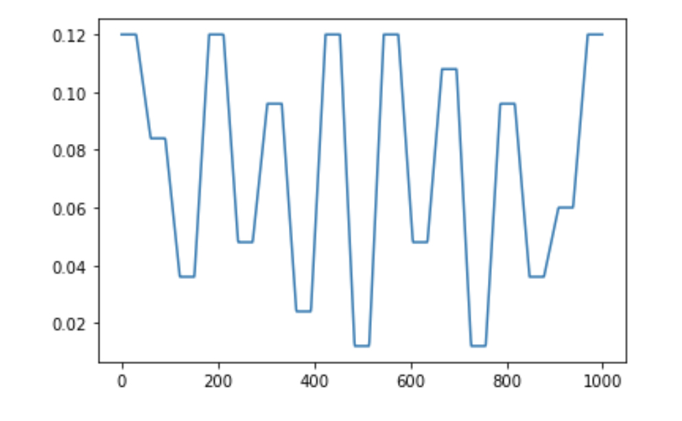
‘Coding by hand’ – I colour coded each level of cut line for each facet and then compared it with previous facets to create a new pattern. These lines are for the mirror facets 13 to 25. The scale of these numbers is in microns
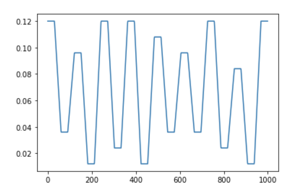
These lines of numbers generated a graph, which visualised the cut paths. This visualisation was part of the Python script that Geoff wrote towards the beginning of the project to translate these numbers into g-code for the nano-lathe to read.
Profile cut for mirror facet #23 (side-view)Profile cut for mirror facet #24 (side-view)
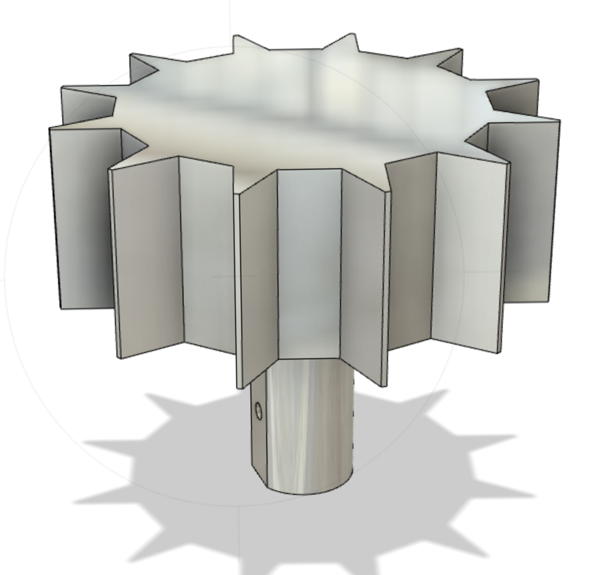
Making the Internal Jigs I modelled the gigs for the facets in Fusion 360. Before I made the facet blanks using the mill, I tested if it was possible to always use the same facet design no matter how many facets or angle within the polygon. Below are the models I printed which sit inside the mirror facets and connect to the motor shaft. The 24-sided jig was hollowed out to remove some of the weight for the motor. These jigs were printed using PLA filament, but I will now print them using a more precise SLA resin printer.
12-sided polygon jig to hold the mirror facets24-sided polygon jig to hold the mirror facets
Pixel patterned facets. Here the pixel size is increased from 1 to 1.5mm and the pattern difference from one facet to the next is more controlled than previous tests
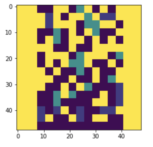
Following on from previous tests with pixelated patterns I wanted to find out if modifying the ‘pixel’ size on the surface of the mirror would create a more distinct projected image. I increased my ‘pixel’ pattern size using Photoshop and then imported these files into Jupyter so that Geoff could help me edit the Python script to generate the g-code for the nano-lathe. Each colour in the pattern represents a specific depth of cut in microns. For example the blue pixels have the deepest profile cut at 120 microns and the green pixels are cut to 60 microns.
‘Pixel’ images created in Photoshop. Each colour represents a different depth of cut, for example the blue ‘pixels’ have the deepest profile at 120 microns and green ‘pixels’ are cut to 60 microns.Colour map generated by Geoff’s Python script from one of the Photoshop images above. This is then translated into a NC format file containing the g-code for the lathe.
Resolving problems of distance from image-object to mirror plane
Projecting the image from the pixelated mirror frame. The image is being projected at a 45 degree angle and therefore only the right half of the mirror frame is effecting the image.
Above is the projected image created by using one of the ‘pixel’ mirror facets. To front-project the image, I placed the mirror at 45 degrees to the image-object (translucent slide), resulting in only half of the mirror surface effecting the projected image. To achieve the optimal reflection of the image-object in the mirror (which is then projected through the objective lens system onto the wall), the mirror needs to be very close to the image-object. Two considerations emerged relating to this required proximity between the image-object and mirror. The first was that to overcome the 45 degree angle issue, I tried using a second mirror to reflect the light in a forward direction. However this doubled the optical distance from the image-object to the mirror facet. The second consideration was that because the mirror facets are part of a rotating polygon, a certain amount of space (a little more than the radius of the polygon) is required for the polygon to rotate without touching the image-object. This means the image-object is too far from the mirror plane. After conversations with Geoff about resolving this issue, we decided to image this image-object just before the surface of the mirror using a wide aperture short focal lens. To make such a lens we needed a large diameter (75mm) relative to its focal length.
50mm acrylic lens blank made by Neil Devlin50 mm acrylic blank in the aluminium, both fabricated by Neil Devlin. The jig is vacuumed onto the nano-lathe spindle during cutting.
Neil Devlin fabricated the optical acrylic blank and aluminium jig for us to use in the nano-lathe. To make the shortest focal length possible we will cut a lens using the full 50mm thickness of the blank. Stay tuned for the result!
Testing 3D image-objects
During the last few weeks I also tested how, using an object instead of a 2D image (translucent slide), effects the projected image. Working from previous image-object works, where I created translucent printed objects to generate projected images in ‘3D’, I was interested if this would have the same effect when using the mirror facets.
This image, depicting an empty space stairwell is pure light. It is generated though a translucent 3D printed object placed in one of my optical image systems.
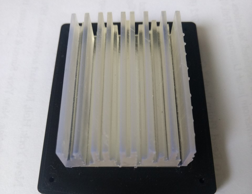
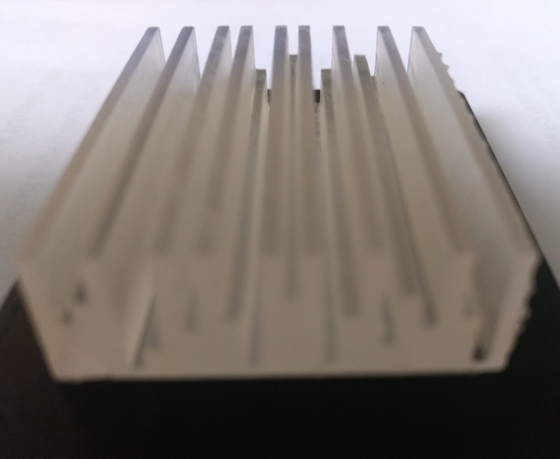
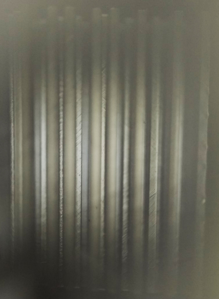
Simulating the 2D lined image that I had previously created in Photoshop, I modelled the 3D image-object using 1.5mm lines of different depths. I wanted to know if the different depth of each line would affect the transfer of light and hence the projected image. This 3D image-object was printed using an SLA Form printer with translucent resin. I discovered that this line object requires optical polishing for it to transmit sufficient light!
Top view of resin printed translucent 3D image-object.Profile view of different depths of the lines for the image-object.Projected image generated through printed ‘line’ object.