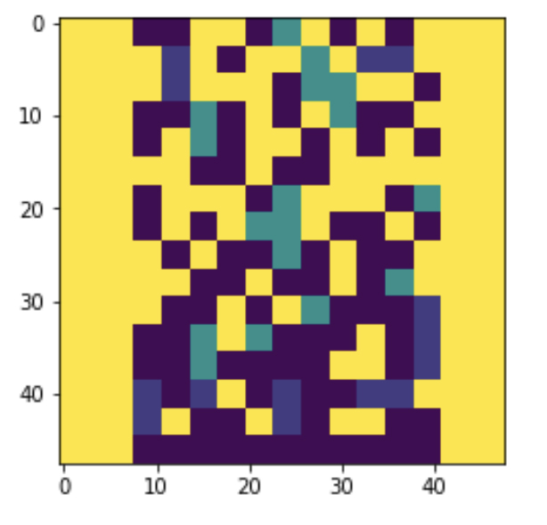
Following on from previous tests with pixelated patterns I wanted to find out if modifying the ‘pixel’ size on the surface of the mirror would create a more distinct projected image. I increased my ‘pixel’ pattern size using Photoshop and then imported these files into Jupyter so that Geoff could help me edit the Python script to generate the g-code for the nano-lathe. Each colour in the pattern represents a specific depth of cut in microns. For example the blue pixels have the deepest profile cut at 120 microns and the green pixels are cut to 60 microns.
Resolving problems of distance from image-object to mirror plane
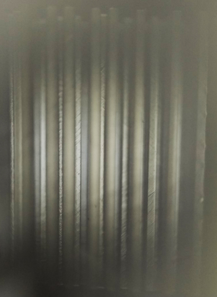
Above is the projected image created by using one of the ‘pixel’ mirror facets. To front-project the image, I placed the mirror at 45 degrees to the image-object (translucent slide), resulting in only half of the mirror surface effecting the projected image. To achieve the optimal reflection of the image-object in the mirror (which is then projected through the objective lens system onto the wall), the mirror needs to be very close to the image-object. Two considerations emerged relating to this required proximity between the image-object and mirror. The first was that to overcome the 45 degree angle issue, I tried using a second mirror to reflect the light in a forward direction. However this doubled the optical distance from the image-object to the mirror facet. The second consideration was that because the mirror facets are part of a rotating polygon, a certain amount of space (a little more than the radius of the polygon) is required for the polygon to rotate without touching the image-object. This means the image-object is too far from the mirror plane. After conversations with Geoff about resolving this issue, we decided to image this image-object just before the surface of the mirror using a wide aperture short focal lens. To make such a lens we needed a large diameter (75mm) relative to its focal length.
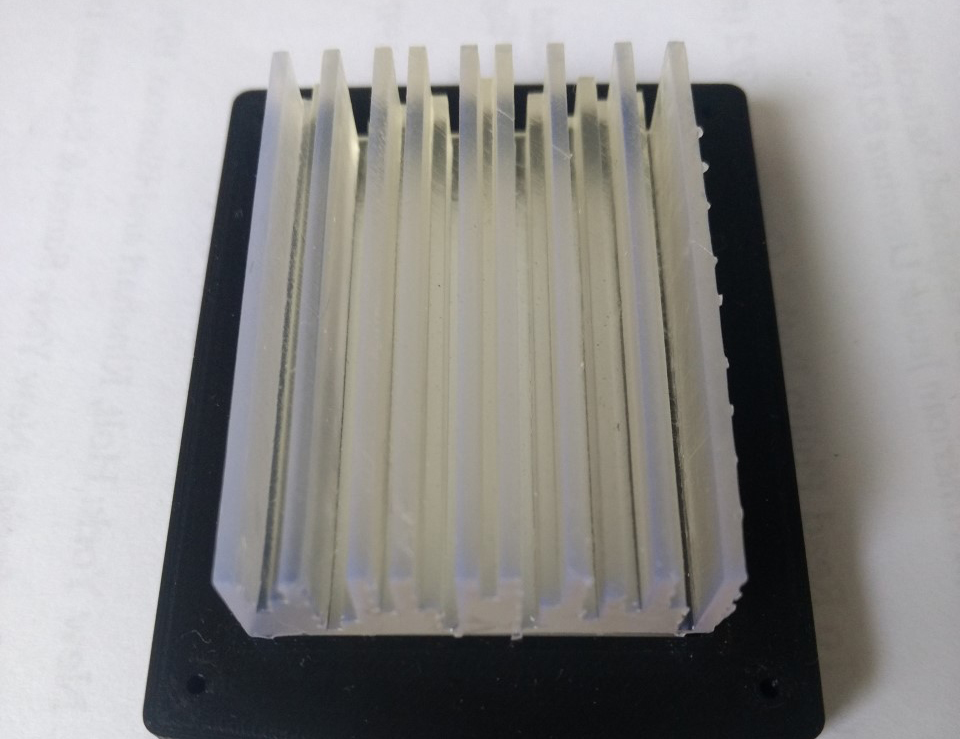
Neil Devlin fabricated the optical acrylic blank and aluminium jig for us to use in the nano-lathe. To make the shortest focal length possible we will cut a lens using the full 50mm thickness of the blank. Stay tuned for the result!
Testing 3D image-objects
During the last few weeks I also tested how, using an object instead of a 2D image (translucent slide), effects the projected image. Working from previous image-object works, where I created translucent printed objects to generate projected images in ‘3D’, I was interested if this would have the same effect when using the mirror facets.
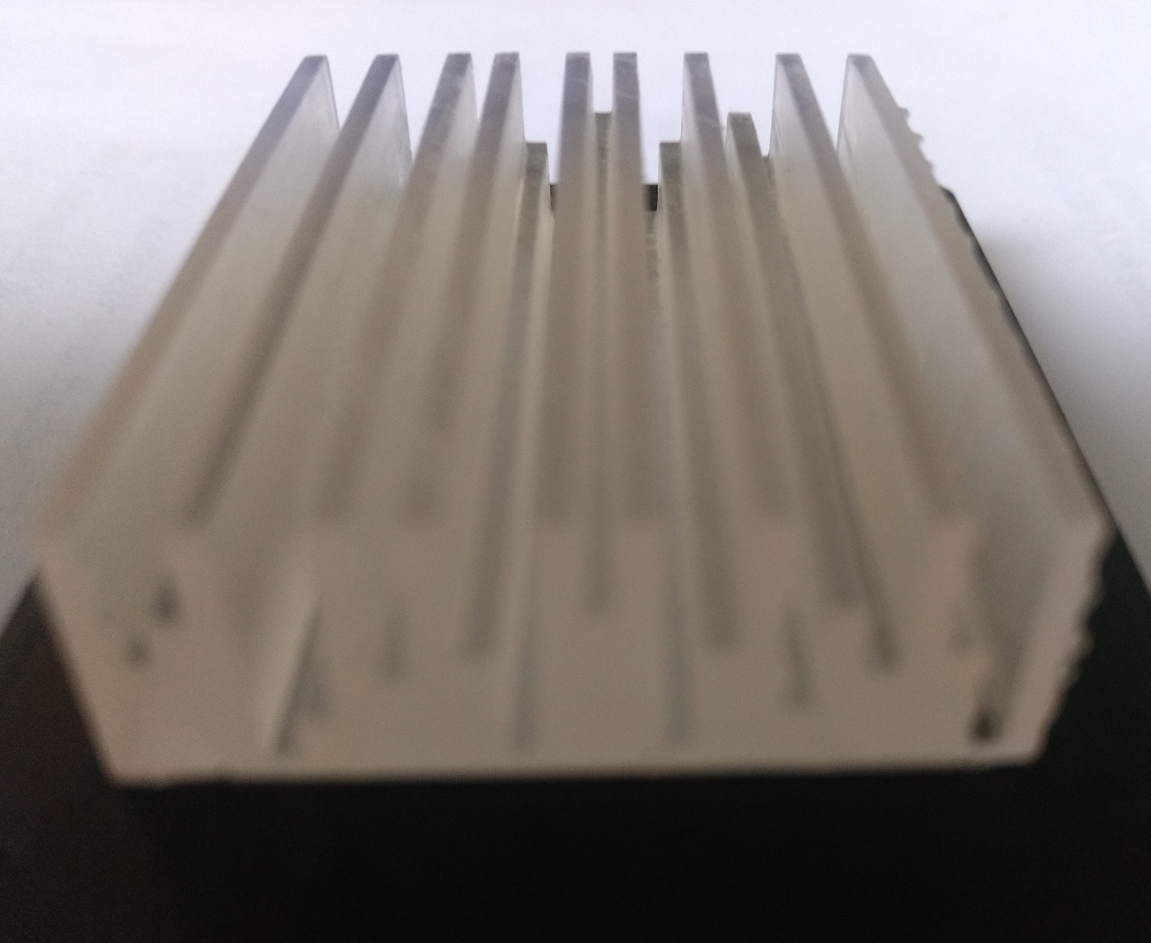
Simulating the 2D lined image that I had previously created in Photoshop, I modelled the 3D image-object using 1.5mm lines of different depths. I wanted to know if the different depth of each line would affect the transfer of light and hence the projected image. This 3D image-object was printed using an SLA Form printer with translucent resin. I discovered that this line object requires optical polishing for it to transmit sufficient light!