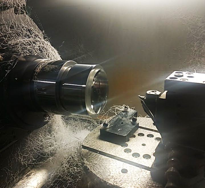
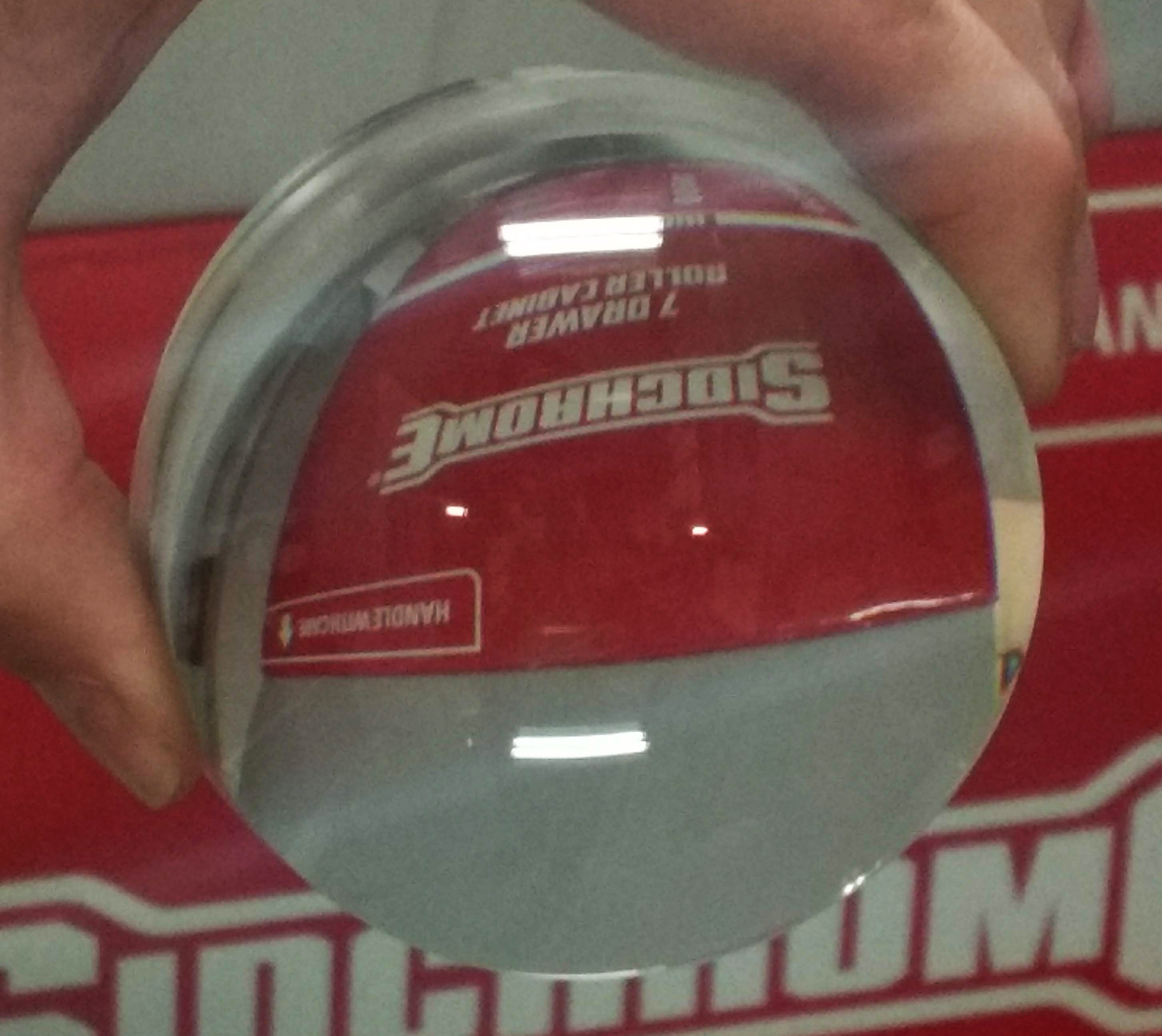
During this week Geoff and myself used the lens blank prepared by Neil Devil to cut a parabolic profile lens. Geoff coded a parabolic curve into the nano-lathe software to generate the .nc file for cutting. We ran a couple of rough passes with the diamond tool to create the curvature of the lens and then optically polished it with a finishing pass. Because we used acrylic, it was much faster than cutting the mirror facets. We completed the top side first and then flipped the lens to cut the other side.
This lens is hopefully the start of our venture into lens making! Geoff and myself are also working with Dr Noelia Martinez Ray to design more accurate curvatures for our lenses. The purpose of this lens is to project an image of the translucent slide so that it focuses just before the surface of the mirror facet.
Translucent image reflected onto the ‘pixelated’ mirror plane.
Both this projected image and the mirror surface are then projected though the objective lens into a combined single image, as per the images I have posted throughout the blog. Below are some images which document the process.
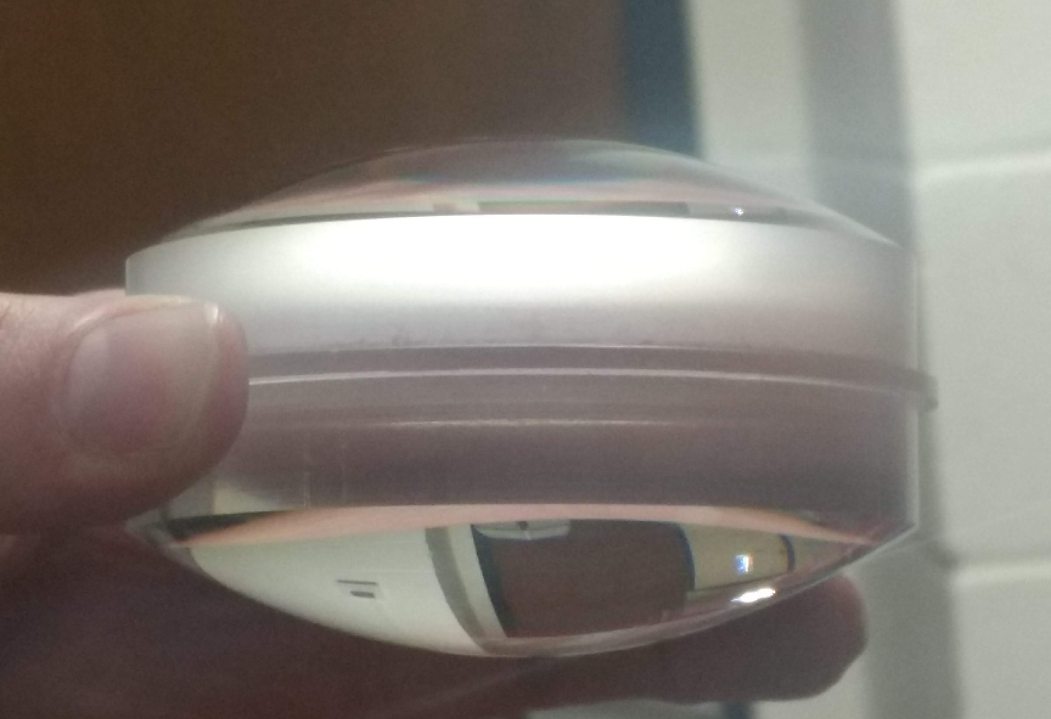
Geoff fixing the flat acrylic disc and jig onto the nano-lathe spindle.The cut and polished lens still attached to the spindle.Optical polished lens.Both sides were cut and polished to crate a bi-convex lens for shorter focal length.Polished lens sitting in the jig.
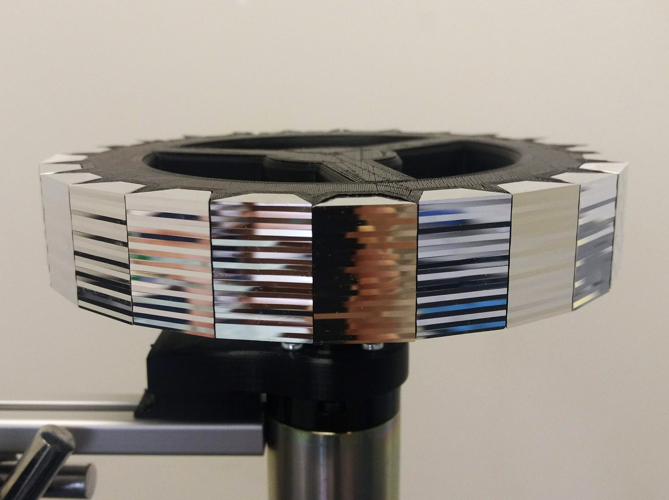
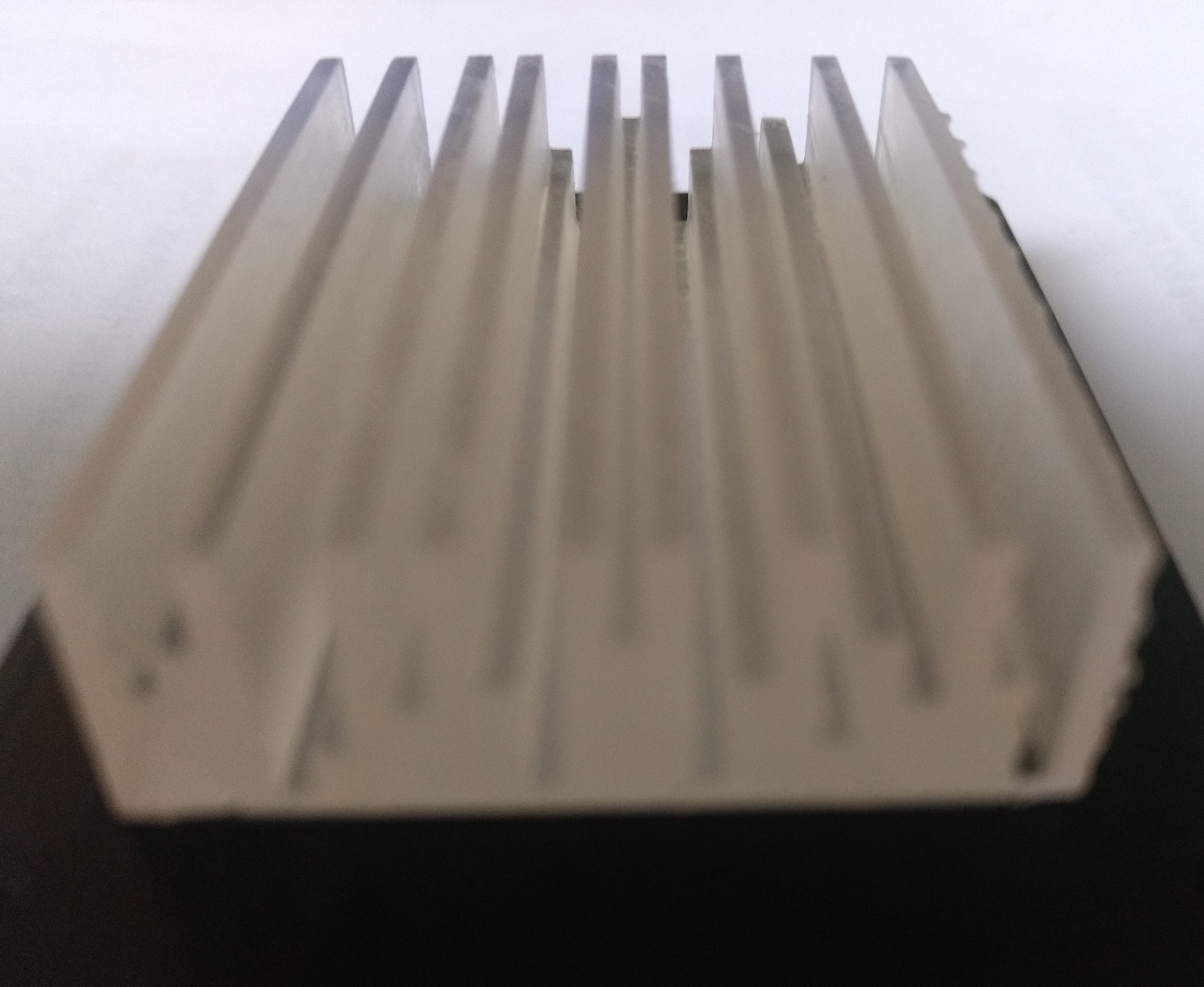
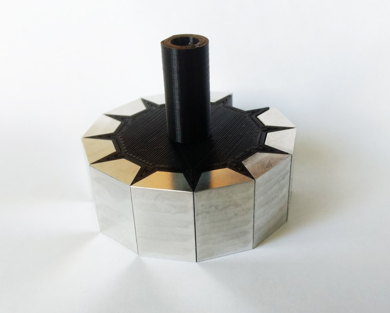
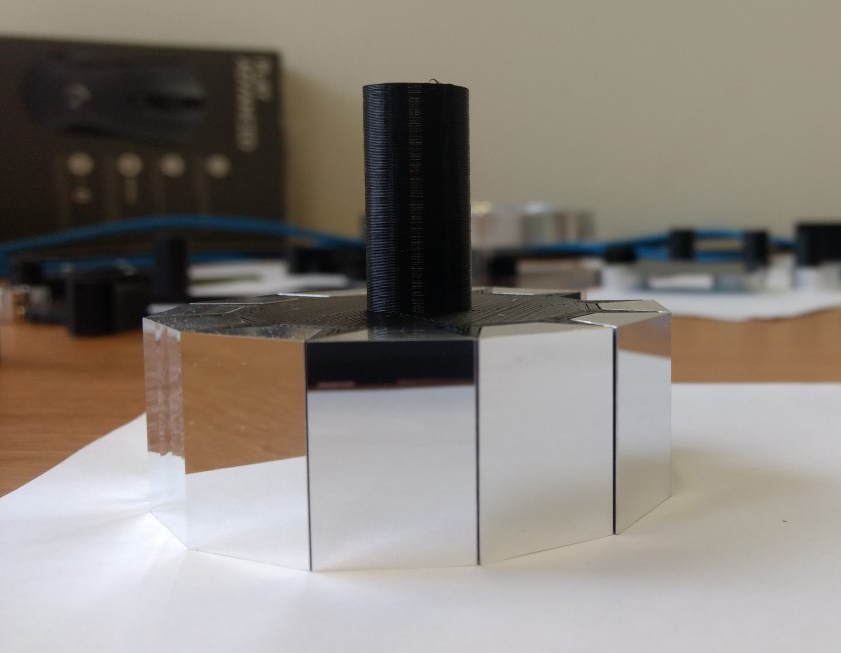
24-sided mirrored polygon. Each facet is cut with a different pattern on the nano-lathe, so that when each facet rotates within the line of the optical system it generates a different image to create the illusion of movement.
Over the past few weeks I have focused on cutting and polishing facets on the nano-lathe. I first began building a polygon with 6 facets, then I increased this number to 12 and now 24. As mentioned in an earlier post, a greater number of facets decreases the angle of rotation and therefore increases the perceptual illusion of movement in the projected image.
When I created the patterns (cut profiles) for each facet I was interested in having a human element in the pattern, as opposed to an algorithm that generated the cut profiles. Perhaps this desire comes from my background as a hands-on maker. During this residency I have used predominantly digital fabrication (nano-lathe, C ‘n C mill, 3D printers), which primarily use Cartesian axes and g-code. Embedded within this computer/machine code I wanted something ‘hand-made’ or perhaps to be more exact, ‘human-made’! This approach makes different patterns to those produced by a strictly adhered to set of computer rules. Apart from the overall intent and aims of the project, it is important that the actual making of the work has some element of embodied physicality. This adheres to how I use my exposed optical image devices to explore wonder – through physical embodied experience. It is this intersection of art, science and technology that really interests me, the inter-space of old and new, digital and material, tacit and computational, and known and unknown.
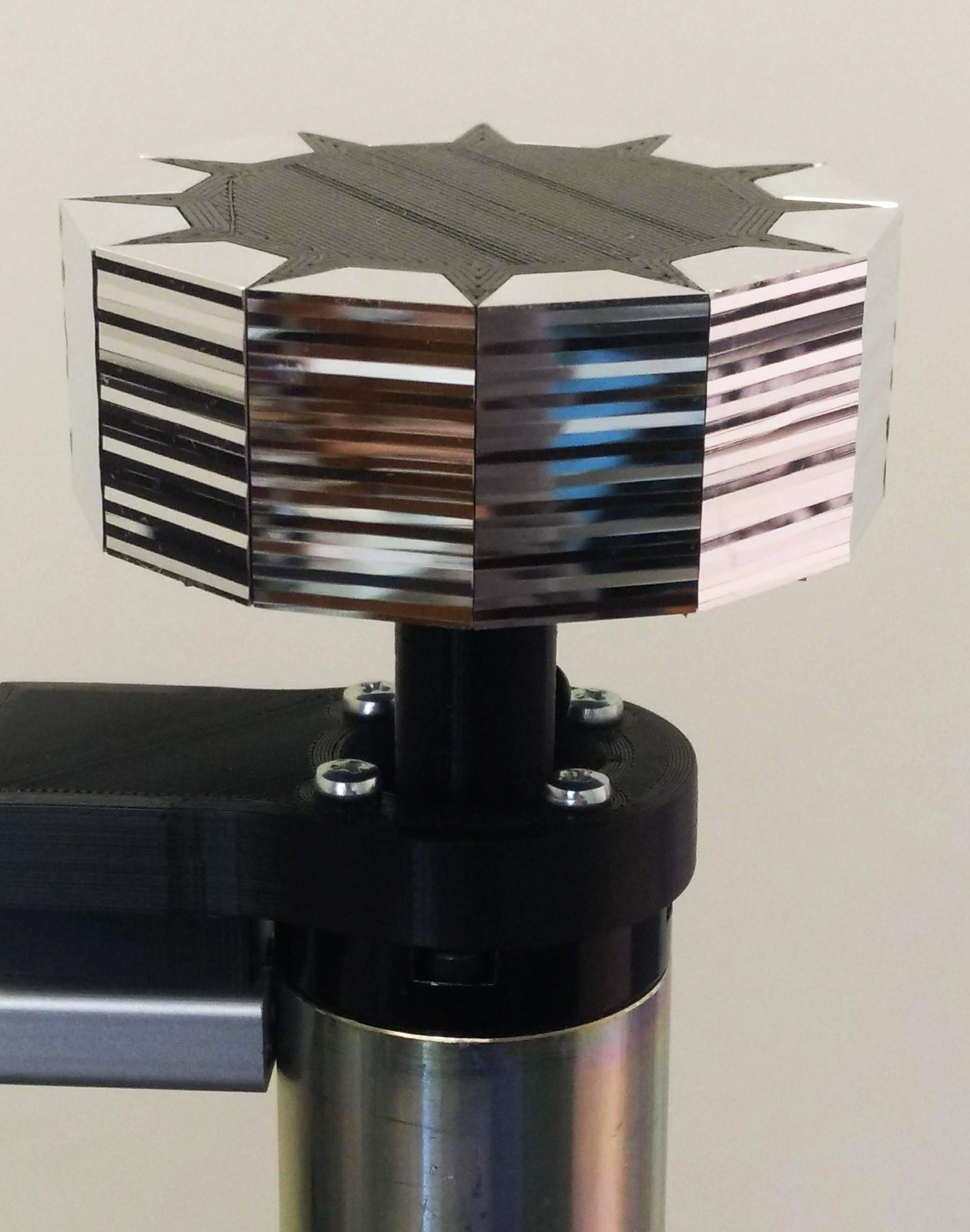
12-sided mirrored polygon
To create each cut profile, I used a very rudimentary process of colour coding. This allowed me to visualise the change of depth in each line cut on the same facet and compare this change to previous facet patterns, when deciding on the next line depth. It reminded me of the phrase of ‘painting by numbers’ – in a way, I was trying to humanise the code and subsequently the profile cuts and moving image.
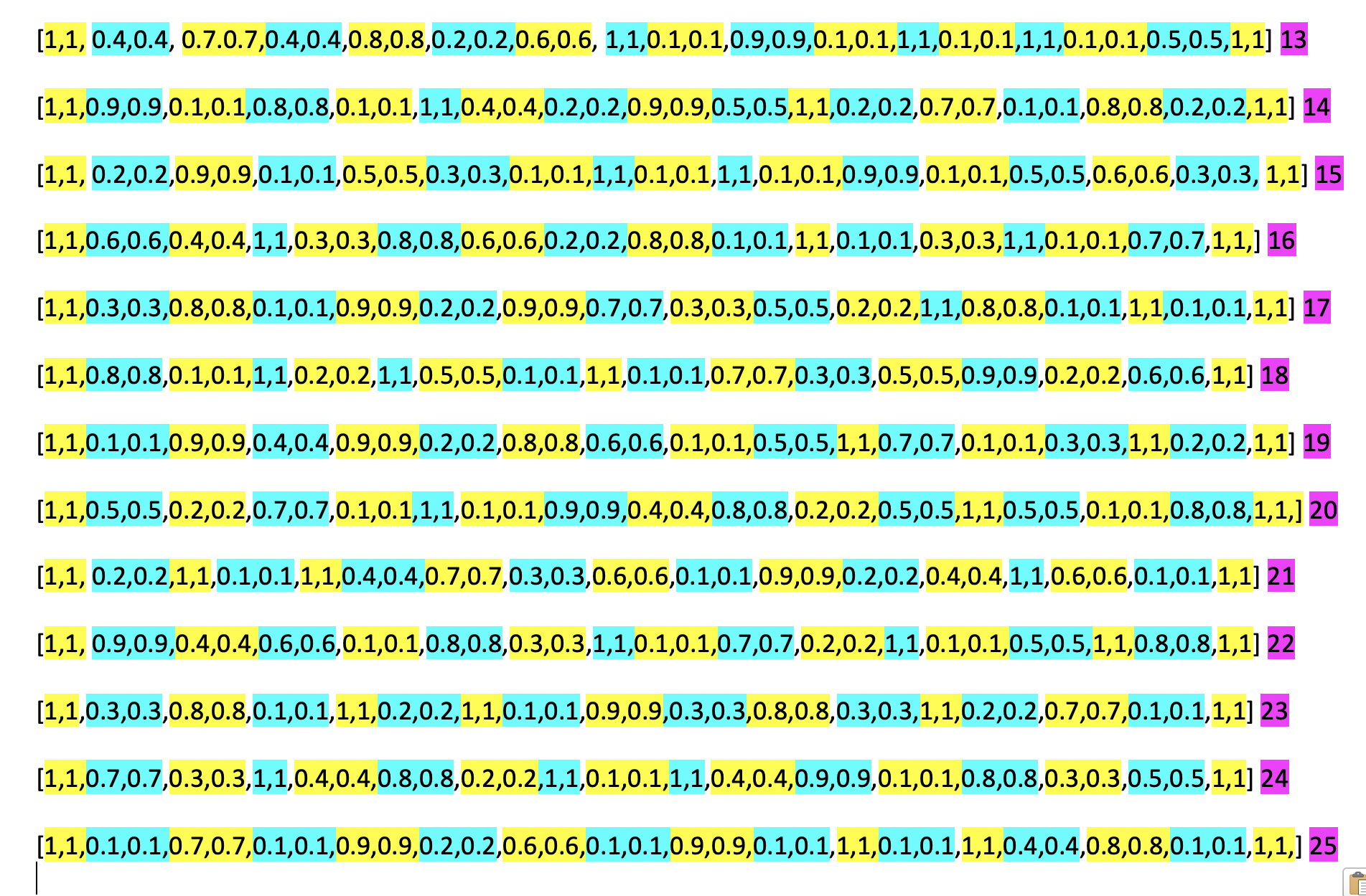
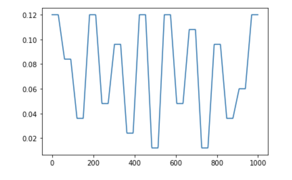
‘Coding by hand’ – I colour coded each level of cut line for each facet and then compared it with previous facets to create a new pattern. These lines are for the mirror facets 13 to 25. The scale of these numbers is in microns
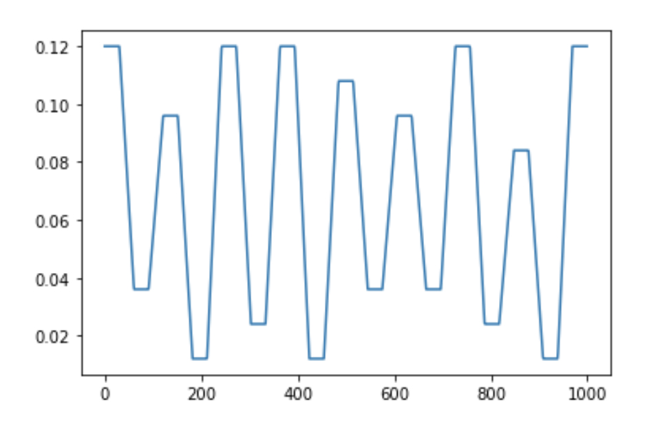
These lines of numbers generated a graph, which visualised the cut paths. This visualisation was part of the Python script that Geoff wrote towards the beginning of the project to translate these numbers into g-code for the nano-lathe to read.
Profile cut for mirror facet #23 (side-view)Profile cut for mirror facet #24 (side-view)
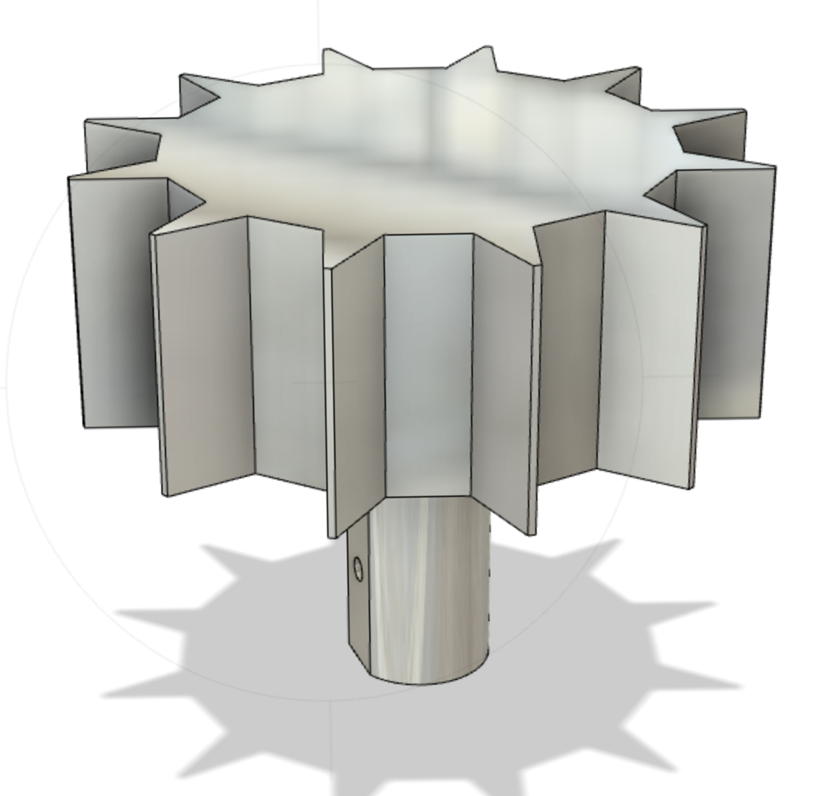
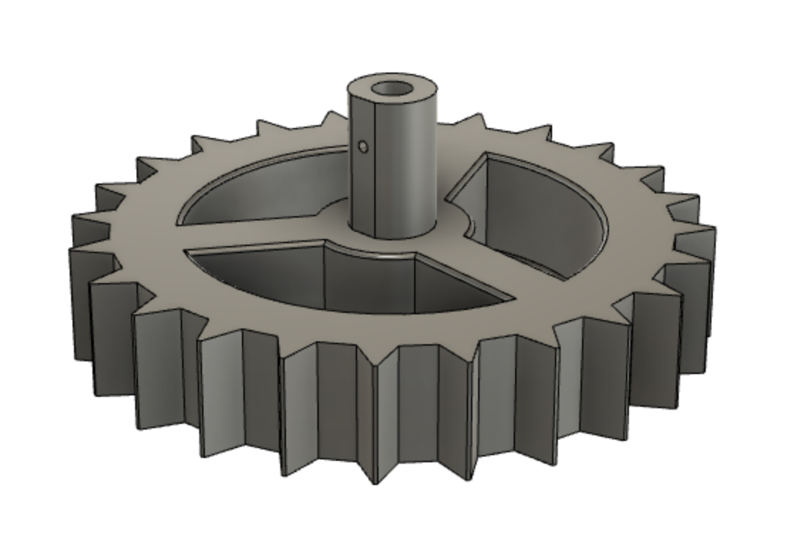
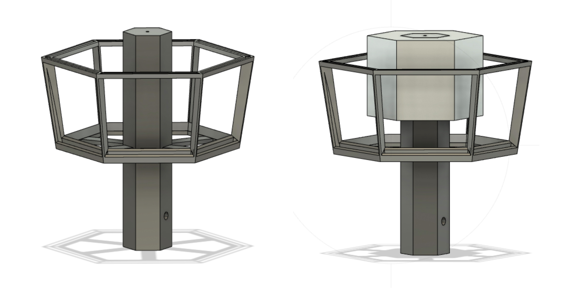
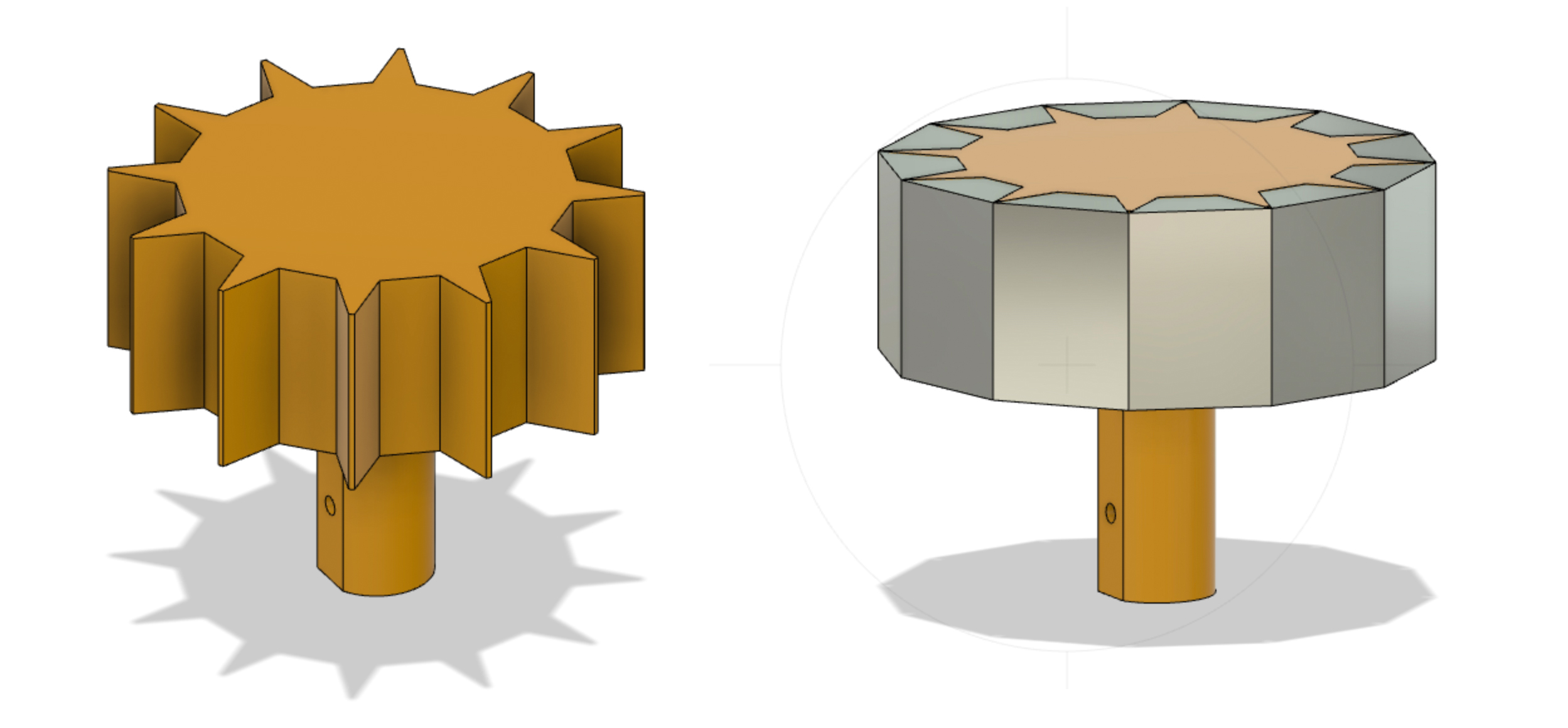
Making the Internal Jigs I modelled the gigs for the facets in Fusion 360. Before I made the facet blanks using the mill, I tested if it was possible to always use the same facet design no matter how many facets or angle within the polygon. Below are the models I printed which sit inside the mirror facets and connect to the motor shaft. The 24-sided jig was hollowed out to remove some of the weight for the motor. These jigs were printed using PLA filament, but I will now print them using a more precise SLA resin printer.
12-sided polygon jig to hold the mirror facets24-sided polygon jig to hold the mirror facets
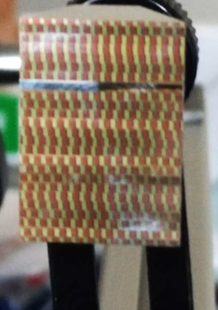
Pixel patterned facets. Here the pixel size is increased from 1 to 1.5mm and the pattern difference from one facet to the next is more controlled than previous tests
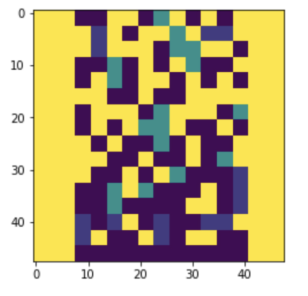
Following on from previous tests with pixelated patterns I wanted to find out if modifying the ‘pixel’ size on the surface of the mirror would create a more distinct projected image. I increased my ‘pixel’ pattern size using Photoshop and then imported these files into Jupyter so that Geoff could help me edit the Python script to generate the g-code for the nano-lathe. Each colour in the pattern represents a specific depth of cut in microns. For example the blue pixels have the deepest profile cut at 120 microns and the green pixels are cut to 60 microns.
‘Pixel’ images created in Photoshop. Each colour represents a different depth of cut, for example the blue ‘pixels’ have the deepest profile at 120 microns and green ‘pixels’ are cut to 60 microns.Colour map generated by Geoff’s Python script from one of the Photoshop images above. This is then translated into a NC format file containing the g-code for the lathe.
Resolving problems of distance from image-object to mirror plane
Projecting the image from the pixelated mirror frame. The image is being projected at a 45 degree angle and therefore only the right half of the mirror frame is effecting the image.
Above is the projected image created by using one of the ‘pixel’ mirror facets. To front-project the image, I placed the mirror at 45 degrees to the image-object (translucent slide), resulting in only half of the mirror surface effecting the projected image. To achieve the optimal reflection of the image-object in the mirror (which is then projected through the objective lens system onto the wall), the mirror needs to be very close to the image-object. Two considerations emerged relating to this required proximity between the image-object and mirror. The first was that to overcome the 45 degree angle issue, I tried using a second mirror to reflect the light in a forward direction. However this doubled the optical distance from the image-object to the mirror facet. The second consideration was that because the mirror facets are part of a rotating polygon, a certain amount of space (a little more than the radius of the polygon) is required for the polygon to rotate without touching the image-object. This means the image-object is too far from the mirror plane. After conversations with Geoff about resolving this issue, we decided to image this image-object just before the surface of the mirror using a wide aperture short focal lens. To make such a lens we needed a large diameter (75mm) relative to its focal length.
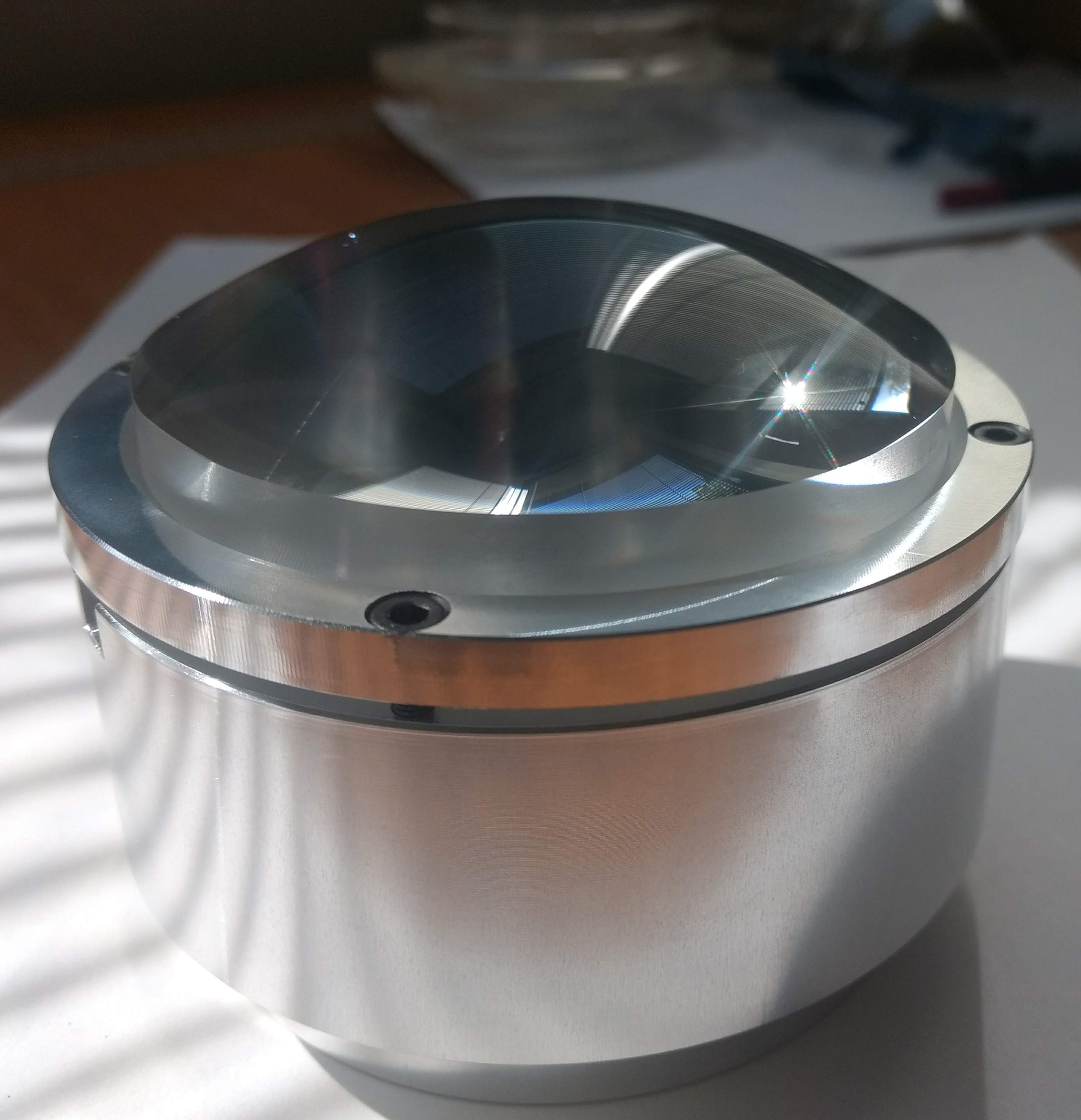
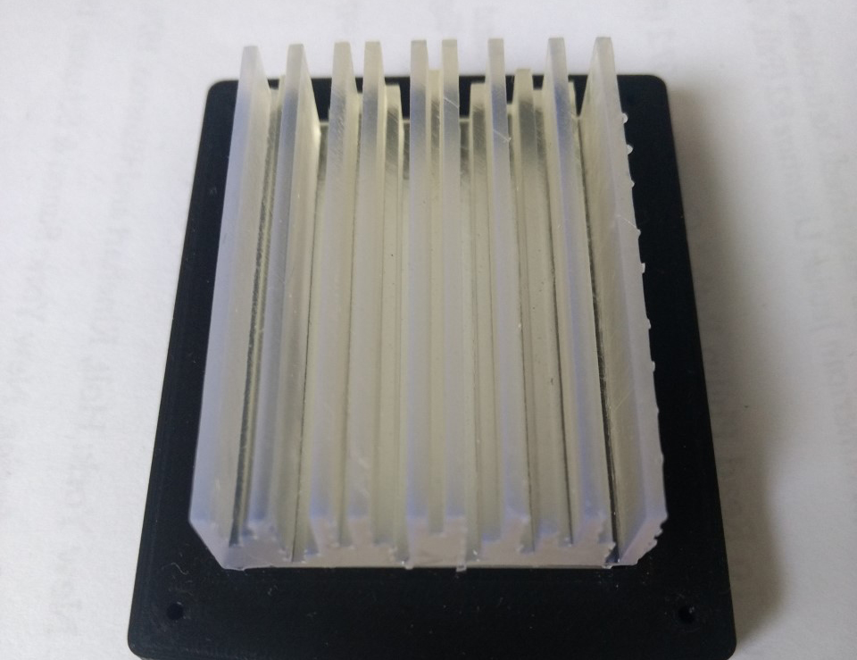
50mm acrylic lens blank made by Neil Devlin50 mm acrylic blank in the aluminium, both fabricated by Neil Devlin. The jig is vacuumed onto the nano-lathe spindle during cutting.
Neil Devlin fabricated the optical acrylic blank and aluminium jig for us to use in the nano-lathe. To make the shortest focal length possible we will cut a lens using the full 50mm thickness of the blank. Stay tuned for the result!
Testing 3D image-objects
During the last few weeks I also tested how, using an object instead of a 2D image (translucent slide), effects the projected image. Working from previous image-object works, where I created translucent printed objects to generate projected images in ‘3D’, I was interested if this would have the same effect when using the mirror facets.
This image, depicting an empty space stairwell is pure light. It is generated though a translucent 3D printed object placed in one of my optical image systems.
Simulating the 2D lined image that I had previously created in Photoshop, I modelled the 3D image-object using 1.5mm lines of different depths. I wanted to know if the different depth of each line would affect the transfer of light and hence the projected image. This 3D image-object was printed using an SLA Form printer with translucent resin. I discovered that this line object requires optical polishing for it to transmit sufficient light!
Top view of resin printed translucent 3D image-object.Profile view of different depths of the lines for the image-object.Projected image generated through printed ‘line’ object.
From top left clockwise: The photoshop file with 1mm pixels; the printed translucent image in the 3D printed holder; mirror facet #8; projected image from mirror facet #9; projected image from mirror facet #9 rotated 90 degrees.
This week I also began testing the mirrors using a series of new images that I made in photoshop. I printed these images onto thin transparent sheet and placed them into my optical system using slidable holders, so I can adjust their position relative to the mirror and lenses.
The translucent image frame in the optical system (in the middle of an LED, condensing lenses and the mirror facet and objective lens)
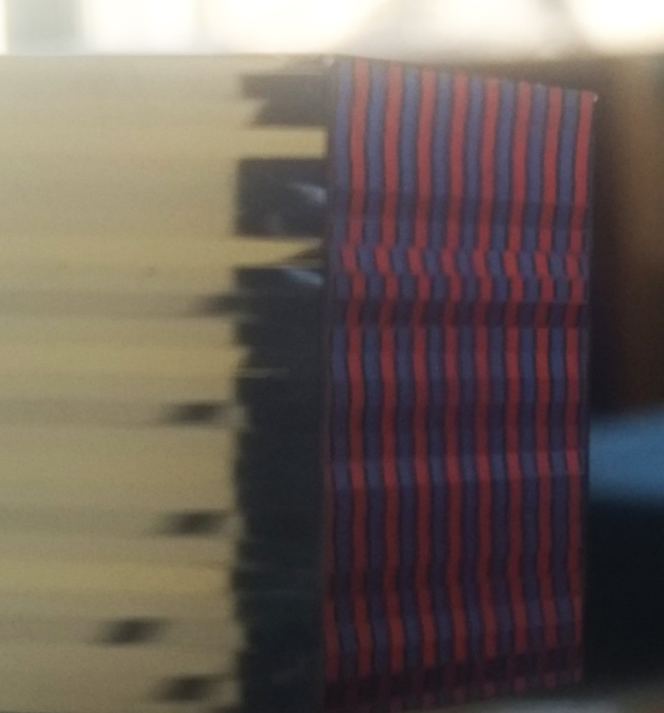
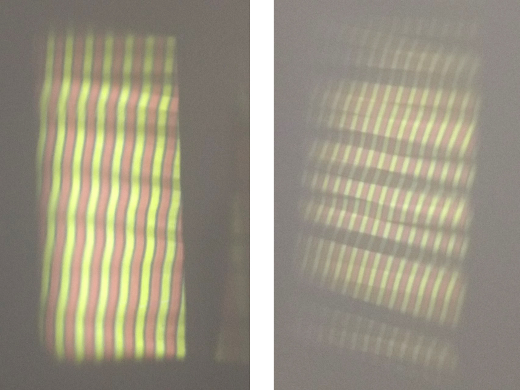
At first I was using multiple colours, then 2 colours (red and green, see the images directly above and below) and then I paired it back to a single colour (see the image at the top of this post) and realised that this was giving me much more information regarding how each mirror was refracting the light in different ways (bending the image). Even by simply rotating the mirror plane 90 degrees, I could generate a different projected image.
From top left clockwise: The photoshop file with 1mm pixels; the printed translucent image in the 3D printed holder; mirror facet #5; projected image from mirror facet #6; projected image from mirror facet #6 rotated 90 degrees.
As I cut more mirror facets I will test each each mirror for tits resulting projecting image. These individual image frames will make up the sequence for the moving image. I am also beginning to test different images, to see how each new image is ‘refracted’ using the cut mirrors.
Projection test from pixelated mirror. ‘Pixel’ size was too small (1mm square), causing too much light scatter and therefore breaking up the image.
I tested the ‘pixel’ cut facets with a series of images, but the resulting projected images were disappointing. The size of the top of each of the ‘pixel’ profiles relative to the angle between them (as one profile cut steps down to the next profile cut) was too small. I discussed this with Geoff and we decided to try a few more tests with slightly larger ‘pixel’ sizes. I had designed the original tests to be 1mm square, we decided to increase this to 1.5 mm square and see what happens to the projected image with these profiles. I will post the outcomes these tests are complete.
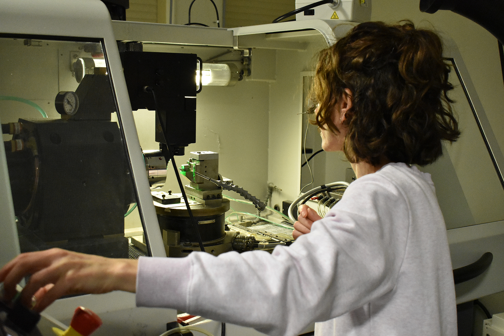
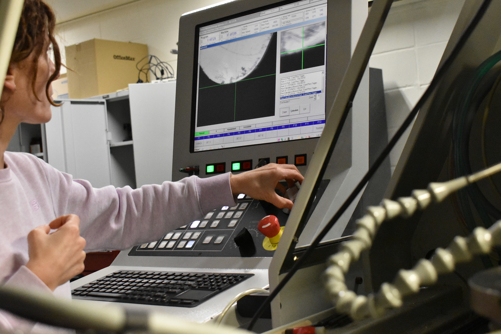
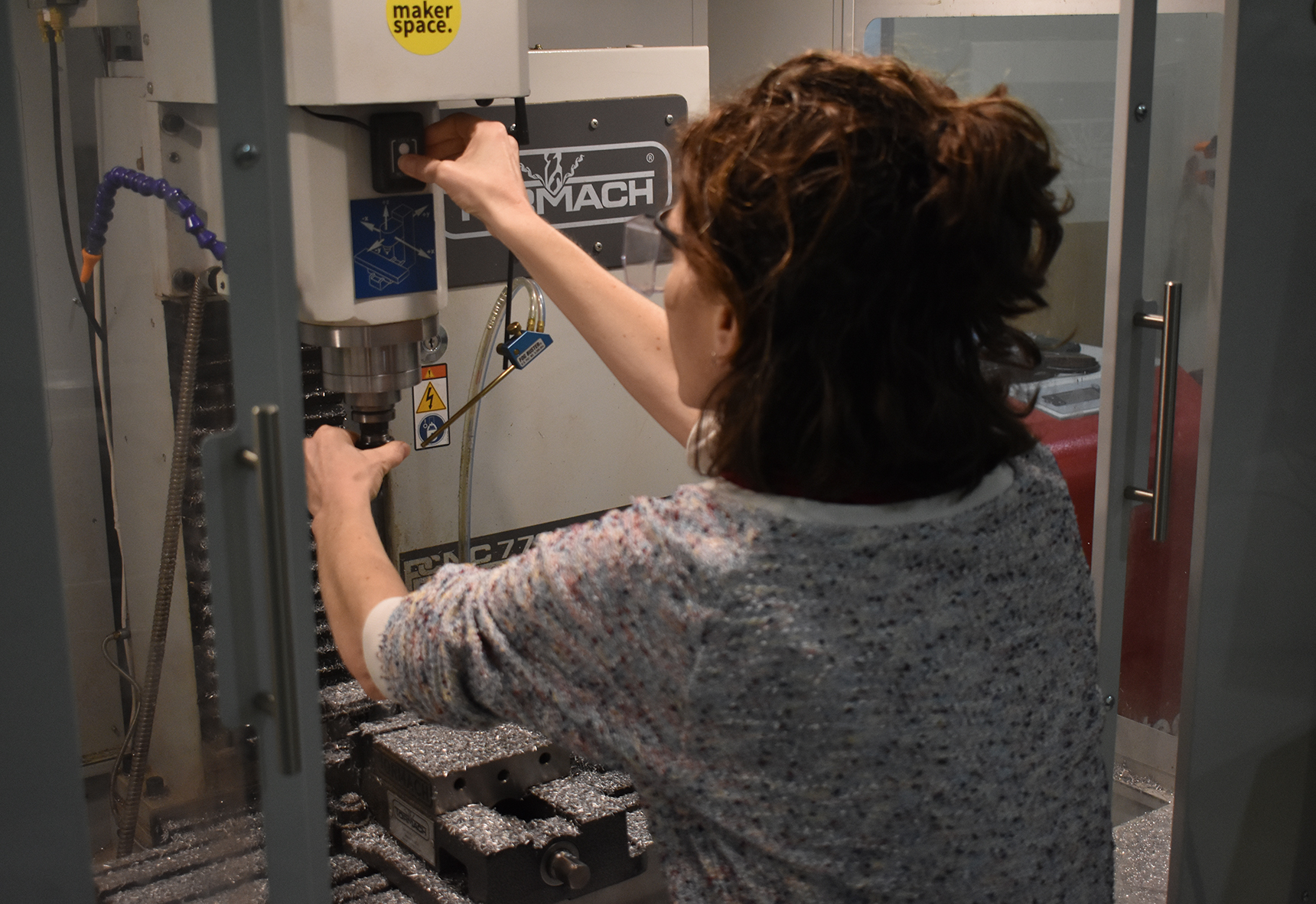
Deirdre preparing the lathe to cut the ‘pixel’ patterned facets. Here I am calculating the ‘trigger’ points on the tip of the diamond tool (using the camera) to locate the centre point of the tool relative to the x-axis and centre of the part being cut.Deirdre locating the ‘trigger’ points on the tip of the diamond tool (using the camera) to calculate the centre point of the tool relative to the x-axis and centre of the part being cut.
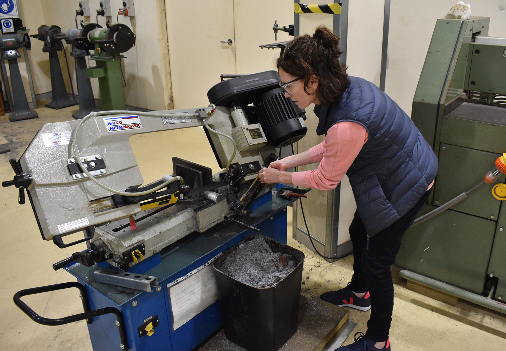
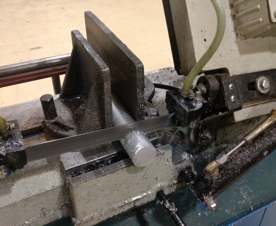
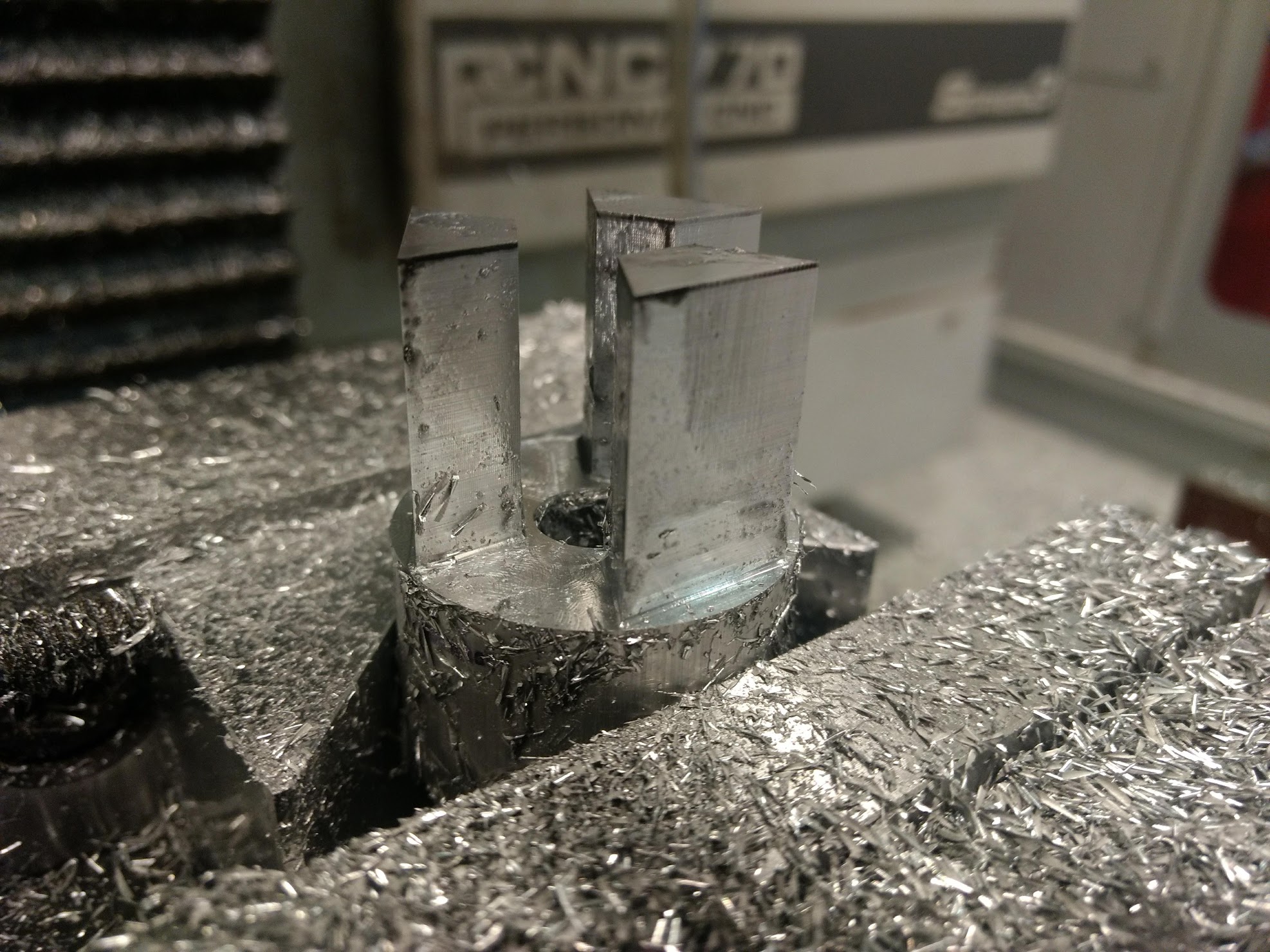
In the meantime I am continuing (as quickly as the nano-lathe allows) with the line cuts. I have developed a more systematic approach in how to cut my facets and am aiming to make as many as I can with the time left on the residency. This has meant making many more facet blanks and I have started a production of facets. Jordan Haddrick from the Maker Space has been helping me with the production run. As introduced in my previous post, we have been making the facets in lots of 3, preparing them on the band saw and lathe and then moving on to the Tormach mill for the profile cutting and finishing.
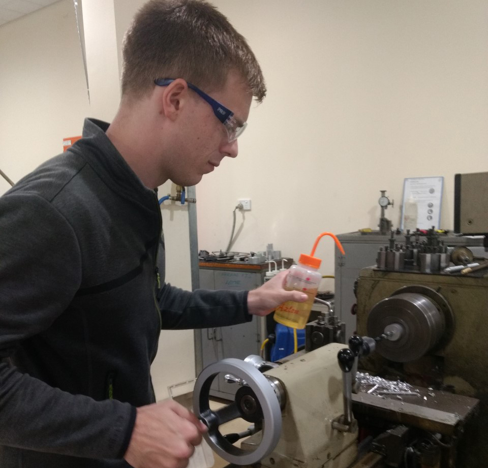
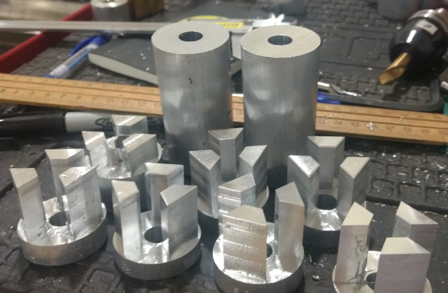
Deirdre on the bandsaw cutting the aluminium lengths for the facets blanks to be cut in the Tormach mill.Cutting the lengths of aluminium rod in preparation for batch making the facets.Jordan drilling the central holes on the lathe. Removing the core material speeds up the cutting time on the mill.The drilled out parts ready for cutting on the mill.Deirdre changing a tool in the Tormach mill.3 facets in the mill. These were removed from the stock using a hack saw and then re-faced and drilled in the mill.Parts cut out on the mill, ready for hack sawing and facing.
After realising that I needed many more than 6 sides per polygon and that each facet would take a minimum of 12 hours to cut on the nano-lathe, I had to rethink some of my fabrication strategy and discuss with Geoff how we might to this.
At the beginning of the project we had discussed cutting a single polygon with multiple facets. But there were problems to overcome with this approach. It would require many days cutting on the nano-lathe and there was also the additional challenge of how to fabricate the blank in preparation for the nano-cuts. If we made it on another machine, it would be very difficult to position the part and the tool on the nano-lathe to match the exact profile the blank’s facets.
We therefore came up with a compromise – to make a smaller polygon with 36 facets each being 10mm high and 10.5mm wide. A blank this size can be cut in the nano-lathe and therefore provide an exact reference for every facet. This will need a few days of cutting, but the time will be significantly shortened due to its smaller size. It will also require a short focal length macro lens to condense the image onto the mirror facet and a lens of greater magnification for the moving image be sufficiently magnified.
Neil made us the blank cylinder to be cut into the polygon form. Our task now is to work out the profile for each of the facet cuts.
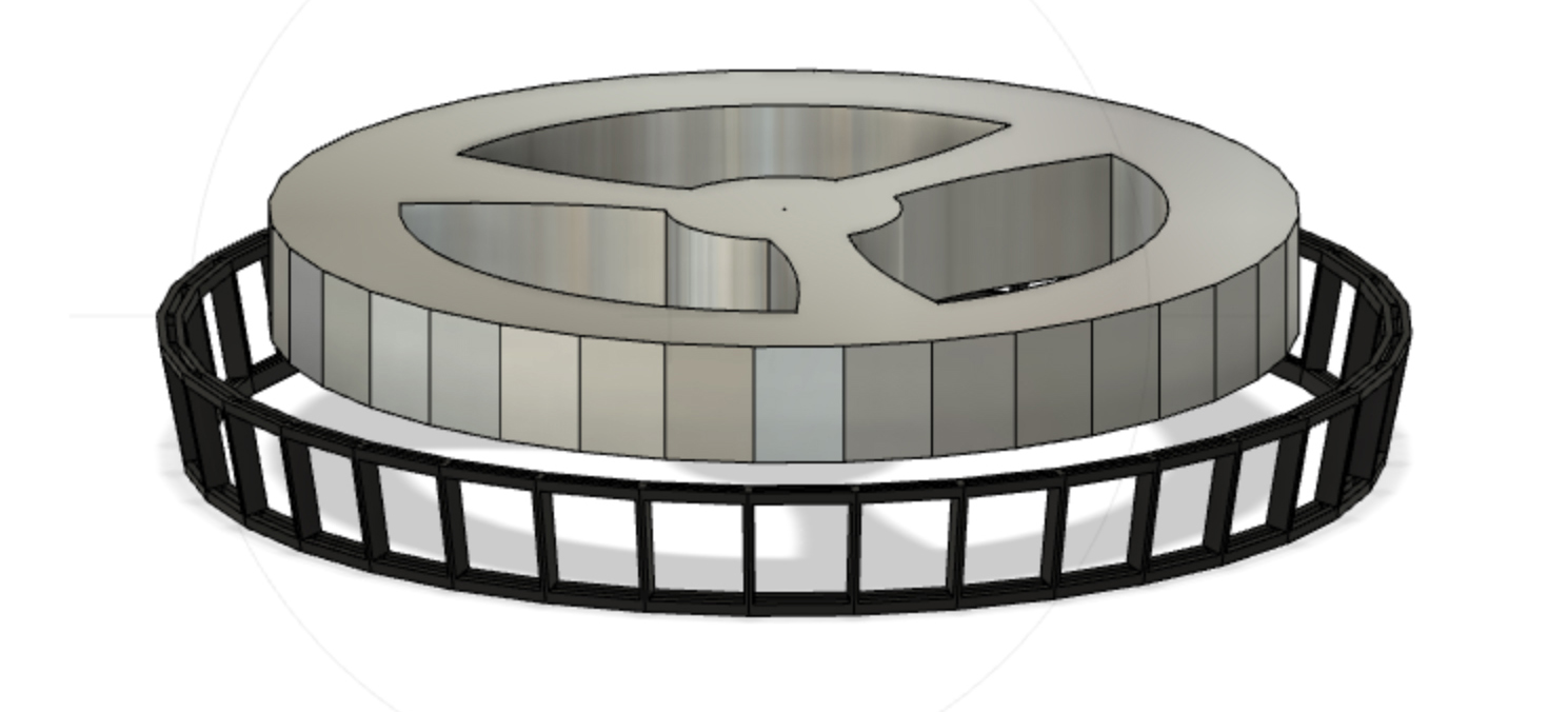
Blank disc fabricated by Neil Devlin for our nano-lathe cut polygon. Neil milled out most of the material in the centre to lighten the form. The disc in the centre serves to hold the polygon, as once it is cut we will no linger be able to touch the sides of the form.Side view of the blank disc for the polygon featuring the stem that fits into the holding jig for the lathe.
Testing new cuts for the 36 frames – changing from lines to pixels
Based on an earlier part that Geoff had cut on the lathe, I wanted to test the idea of using ‘pixels’ instead of lines on the mirror’s surface. I created a depth map in Photoshop, using 1mm square pixels, with each colour designated a different depth of cut.
‘Pixel’ facets cut by Geoff on an earlier test.
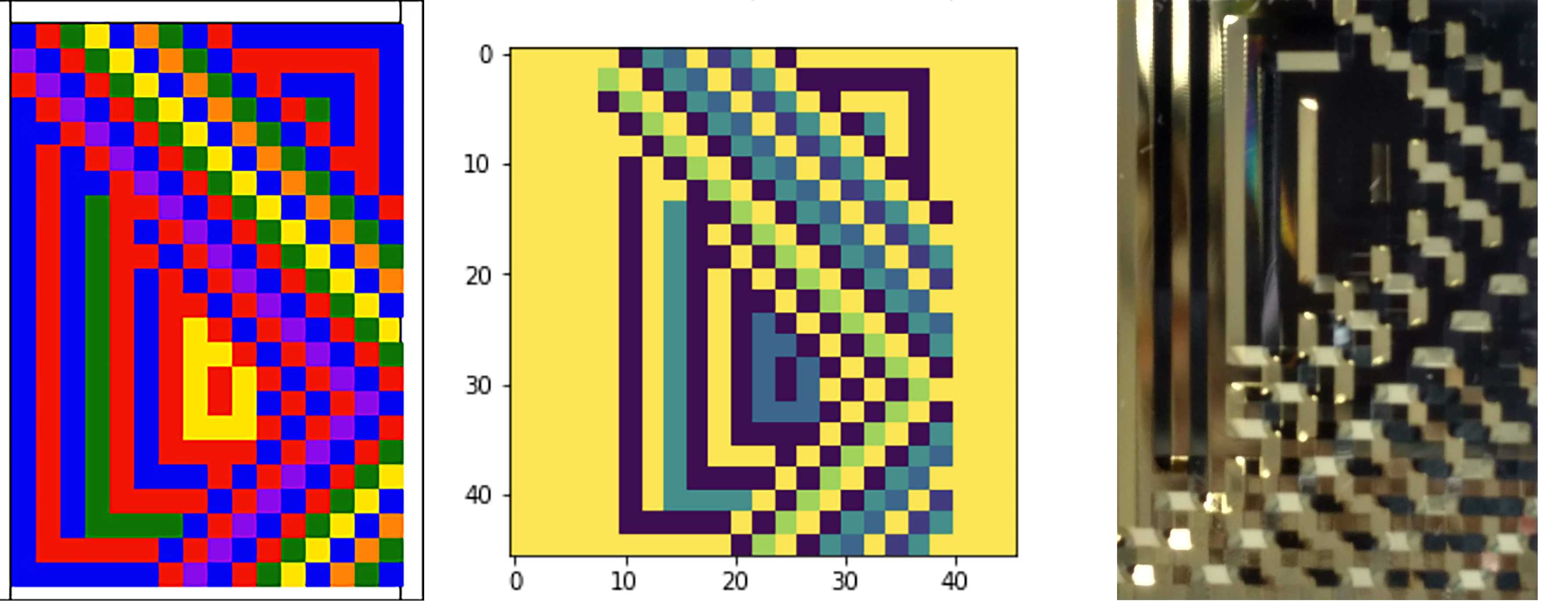
Geoff then translated this map into Python and I ran the script, exporting it out as an NC file to generate the g-code for the lathe. The images below show the transition from photoshop file, to the visualised python script, to the cut mirror facet. Next comes testing these facets with a matching translucent image!
Mirror facets cut on nano-lathe using a ‘pixelated’ pattern
Increasing the number of aluminium facets (blanks, unpolished) from 6 to 12 around the 3D-printed jig
After testing different motors, (both stepper and DC) at different speeds to rotate the polygon, I couldn’t find an optimal speed to generate the illusion of movement in the moving image. I spent time researching why this might be the case and then I realised that it wasn’t only dependent upon rotational speed and the viewer’s perception of vision (as I wrote about in a previous post). It was also depended upon the relation between the speed of the polygon and the angle that each facet rotates within the optical system.
My previous work with mirrored polygons and moving images had used 48 frames. However for the ANAT project, because the creation of the mirrored facets was much more complex (patterned as opposed to flat facets), I’d been working with six-sided polygons to learn the nano-lathe and work out the optics. Therefore every facet is required to rotate 60 degrees to position itself in front of the optical system. I thought that increasing the rotational speed would solve this issue. However, after testing the polygon with a faster motor speed, I found a threshold for rotational speed and the moving image becomes an indecipherable blur!
I decided to increase the number of facets on the polygon – to reduce the angle of rotation and investigate if the ratio of the angle of rotation to the rotational speed is critical to the perception of movement for the viewer. I used the last of the blanks Neil Devlin had fabricated and I designed and 3D-printed a jig to connect to the motor shaft and hold the aluminium facets.
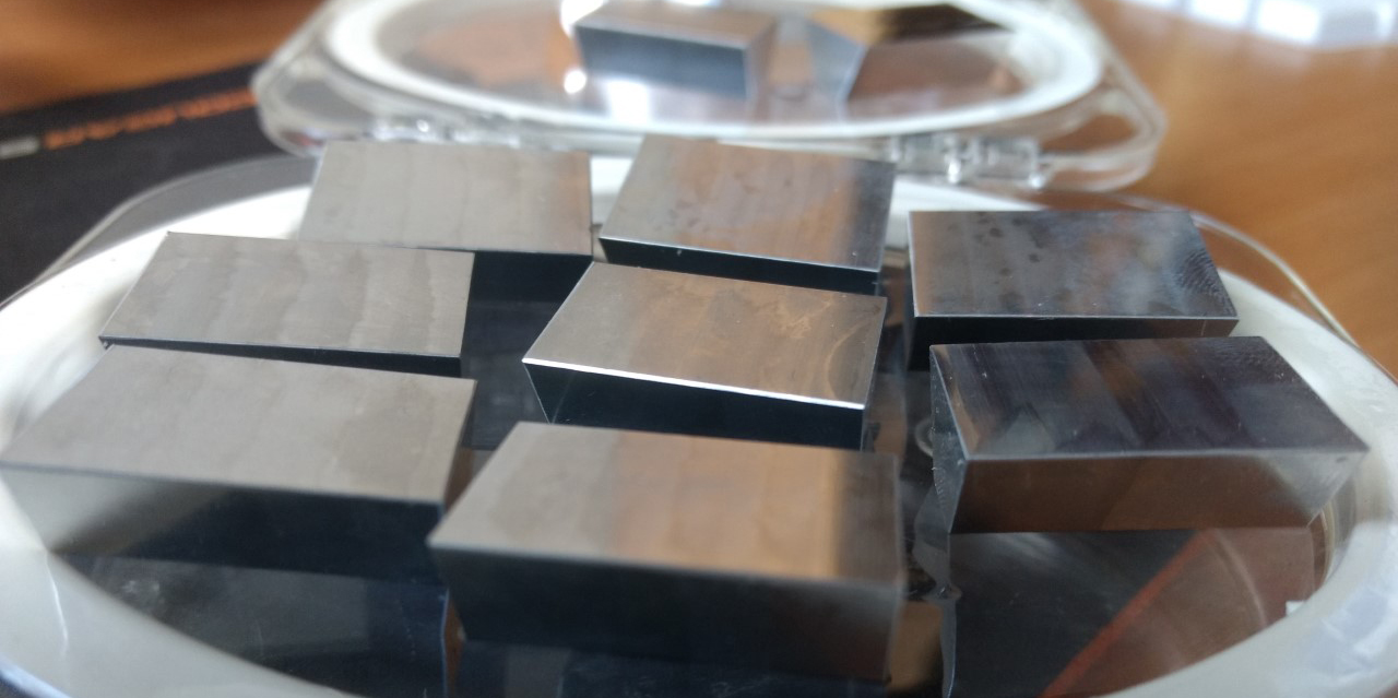
Extra aluminium facets to be cut and polished on the nano-lathe
Testing with plane mirrors rather than cut mirrors Because each facet takes approximately 12 hours to cut, I decided to use a faster way of working out the minimum number of facets. This method uses multiple image frames as well as mirrored facets. Moving from 6 to 12, 24 and 36 frames I modelled up a series of mirrored polygons and image frames holders which would rotate around a single shaft to generate the moving image. This is based on the 19th century technique used by Charles-Émile Reynaud (see previous posts) and which helped form my idea of using multiple mirror facets and a single image frame.
6-sided carousel and mirrored polygon12-sided polygon and inner shaft12-sided polygon and inner shaft wit surrounding 12 frame image carousel. All rotate on a single shaft.
I polished as many facets as I could and then realised that I would need to make many more in order to test the moving image.
Extra polished facets around 12-sided 3D-printed jig
I wanted to learn how to make them using the C ‘n C Tormac mill in the Maker Space. Jordan Haddrick, all round technical guru from the Maker Space inducted me on the machine. Like the nano-lathe, its a steep learning curve for me as I enter back into the Cartesian world of x, y and z planes! Jordan was very generous with his time assisting in the first production run of the facets and soon I hope to be up and running independently on the mill.
3 facets in the mill. These were removed from the stock using a hack saw and then re-faced and drilled in the mill.
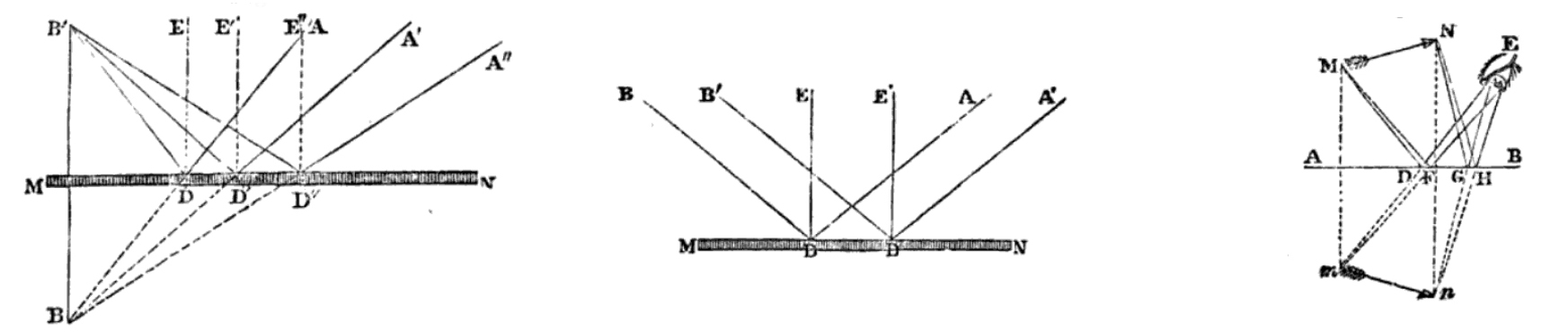
Ray Diagrams featuring plane mirrors in David Brewster’s ‘Treatise on Optics’ (1853).
In an earlier blog post I wrote about how my gaze had zoomed in to accommodate the nano-scale of the lathe and how I adapted my ‘visual thinking’ to a Cartesian reference system of x, y and z axes. Over the past week I have zoomed back out again, reflecting on how my project with Geoff relates to the bigger picture of interweaving art and science. So far, our project has been focused on technical elements: learning the nano-lathe, cutting the components, figuring out the lenses and how to make them, rotational speed and motor electronics. What has also come into play is how the rotational speed of the image frames interacts with human perception to generate the illusion of movement.
The desire to create perceptual illusions appears incongruous with the work of the physicists who surround me – applying their objective/empirical research of nano-scale optics to ‘real’ contexts such as computing and advanced scientific instrumentation. Making work in a scientific environment has led me to think about how different terms have different meanings/understanding across disciplines. The process of cross-disciplinary exploration has also expanded my understanding of how things function and are perceived in the world – two very different concepts, which have been combined and exploited by both natural magicians and artists for centuries.
It’s interesting that ever since the 17th century we have increasingly relied on the scientific apparatus or measuring devices as observational tools (rather than the human observer) for understanding physical phenomena. During the time of the natural magician and preternatural philosopher Giovanni Batista Della Porta (see my first blog post), an observer paying close attention (possibly with the aid of a magnifying lens) was still considered a reliable method of studying natural phenomena. In the wake of the perceptual scepticism[1] that developed during the 18th and 19th centuries, the human perceptual system, deemed too fallible, was eclipsed by the scientific apparatus. As art historian Barbara Stafford writes, “spatial and kinesthetic intelligence… [was] radically divorced from… logical mathematical aptitude”.[2] During this project I have found myself constantly oscillating between the ‘logical mathematics’ of the mirror facets and lenses (ray diagrams, law of refraction, python and gcode) and my ability to perceive illusionary movement in the projected images. And even with the ‘mathematically’ cut components using the precision of the nano-lathe, it is still by trial and error where I physically place the components in the overall optical system. I need my senses as well as mathematics to understand if the experimentation is working or not.
Testing the physical placement of the components in the optical system by trial and error.
I noticed different understandings across across art and science through my exploration of virtual images. In a visual art context, we normally understand a virtual image as something that exists through the combination of the viewer’s perceptual system and a technological apparatus. I think of the 3D images generated through Charles Wheatstone’s 19th century stereoscope or the constructed 3D world presented for a contemporary viewer wearing VR goggles.
Charles Wheatstone’s mirror stereoscope constructed by optician R. Murray (c. 1832).
Cultural historian Amanda Schubert defines her understanding of a virtual image by using the example of the stereoscope. She writes:
The image of depth and relief that the spectator sees when she looks through the stereoscope does not exist in the apparatus itself, nor in the two-dimensional stereograph. Rather, it exists in her perception while she is looking through the stereoscope at the stereograph. Unlike a photographic image, which has material existence as a chemical reaction preserved on sensitised paper, a virtual image like that seen through the stereoscope is irreducible to its material components.[3]
Our project explores the virtual image in a similar way, where the movement of the image and its depth of field) depend on both the technical apparatus (nano-lathe cut facets, rotating polygon and lens system) and the viewer’s perception.
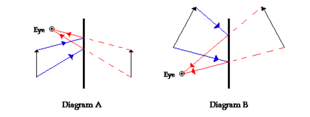
Contemporary ray diagrams from the Physics Classroom (https://www.physicsclassroom.com/class/refln/Lesson-2/Ray-Diagrams-for-Plane-Mirrors)
In the world of Physics, a virtual image is something completely different. It is an image that is formed where light does not actually reach. An example of this is an image reflected on a plane mirror. The reflected image appears to the observer to be behind the mirror plane, that is, not sitting on the mirror’s surface but at a distance away from it. Light however does not actually pass through the location on the other side of the mirror, it only appears to the observer that light (the image) is coming from this location. Although I have never seen it stated in ray optics textbooks (I’ve been trawling through historical and contemporary volumes during my residency!), I would describe this phenomenon as a sensory illusion. I’ve learned that although the optical ray diagrams include the human eye, they focus more on the rays of light and not the whole perceptual system of the viewer.
Clearly, our project also involves this type of virtual image. We are using plane mirrors cut on the nano-lathe to construct the polygon. By cutting different depths into the mirror plane, we are exploiting the virtuality of the image, creating the illusion that the image is emerging from different locations behind the mirror, thereby changing/manipulating the reflected image.
Virtual image reflected on the plane mirror. The nano-lathe cuts give the virtual image the appearance of having a depth of field.
Staying within the world of Physics, a projected image on the other hand is termed a ‘real image’ because with a projected image the light passes through the actual image location, (which for our project, it is the screen or the wall). Contrastingly in the context visual art, a projected image is sometimes termed ‘virtual’ because it is not ‘real’ relative to other material forms of images such as a photograph.
It’s been interesting to discover that I’m working with different disciplinary understandings of virtual and real images and that the combination of how materiality and light work together with human perception and experience, allows me to explore a combination of what is real, virtual and illusionary. It’s becoming clearer how blurry the disciplinary lines of this project are! With our project, one cannot separate fact from fiction, the real from the virtual or even materiality from perception. It is an entanglement of traditional optics, fictional aesthetics, innovative application of digital (nano-) fabrication and visual perception.
[1] Barbara Maria Stafford, (1994) Artful science: enlightenment, entertainment, and the eclipse of visual education, Cambridge, Mass: MIT Press, p8.
Gig made by Neil Devlin to hold the lens blanks for cutting on the nano-lathe.
While waiting for the new DC geared-motor components to arrive, I began conversations with Geoff about cutting some lenses on the lathe – a very exciting prospect for me, with my glass-making background!
Machinist Neil Devlin made some lens blanks from the optical acrylic I sourced and a gig to hold them on the lathe. The gig was specifically designed to fit the lathe spindle and allow me to flip the lens to cut the other side without touching the newly polished surface. It’s been a great learning experience working with Neil. When I provide him with models and drawings, we have follow-up conversations to refine any oddities in the designs and functions of the components. As a maker, I never cease to be amazed by his ingenuity and skill as a machinist engineer.
Optical acrylic lens blank made by Neil Devlin
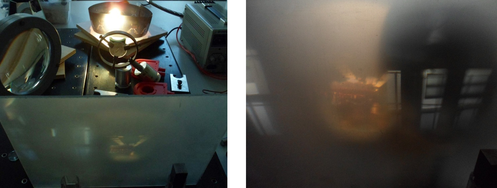
Geoff and myself then worked out the focal lengths and curvatures of the lenses. We knew that we would need at least one lens with a long focal length (to project and magnify the image from the polygon facets). This would need to be a thin lens with a large radial curve. I set up the components in the optical system (LED, condensers, image frame, mirror facets, objective lens) to roughly calculate the distances between the image frame, the mirror and the objective lens and the lens and the projected image. It was tricky calculating each distance, but by trial and error, moving the position of each component systematically, we finally got our projected image.
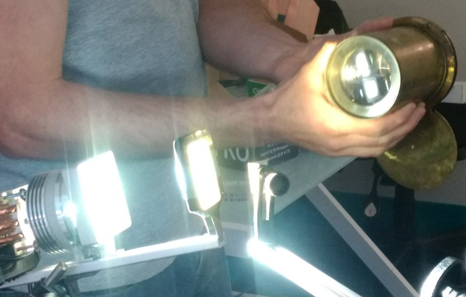
Geoff holding an old magic lantern lens to project the image so we can measure the required focal lengths for our bespoke nano-lathe lens making.Images projected from the mirrored facets, through the objective lens onto the wall. The change in the direction of the red and yellow lines is caused by the different depths of cut on the mirror facet, which are then magnified by the objective lens
The mirror needed to be very close to the image frame. However because the mirror facets will be in motion (as part of the slow moving polygon), it’s better that the polygon is located at a certain distance from the image source (to avoid collision with the image frame). We decided therefore to use an extra short focal length lens to image the reflected image first (which would be at the specific location of the polygon facet) and then project that image into our objective lens to be magnified and projected. This requires a relatively thick lens to refract, demagnify and focus the light rays at a short distance from the centre axis of the lens.
New Collaborator
To work out how to specifically design the curves and thicknesses of the lenses and to avoid any form of chromatic aberration, we used an optical software Zeemax. This however was outside of Geoff’s area of expertise. I’m delighted that Dr Noelia Martinez Rey, a post-doctoral fellow who specialises in adaptive optical systems at the Research School of Astronomy and Astrophysics is keen to come on board as a collaborator. She will help Geoff and myself design the lenses for the polygon image system. Noelia is an expert in Zeemax and will use it to design both the single short focal length lens and the composite objective lenses. For the latter she will design a single lens rather than the usual 2- 3 lenses usually required for objective composites. We will fabricate her designs using the nano-lathe. I am very excited to see these lens outcomes!
Now that I’ve got the hang of the nano-lathe and have been cutting the remainder of the polygon facets, I needed to venture into the world of controlled motor speeds to test the mirror facets in the optical system.
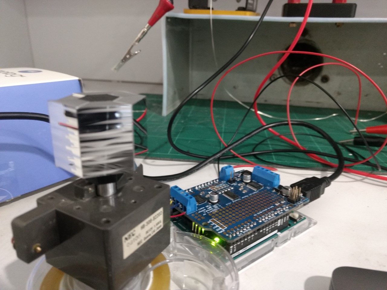
Rotating the polygon facets at very slow speeds has turned out be more complicated that I thought, especially as I’m using a small sale motor. I’ve been working on solutions with Dennis Gibson and Luke Materne in the Electronics Unit of the School. We’ve been building and testing various motor speeds using small steppers, PCBs and Arduino and then moving onto geared DC motors. So why is a slow rotational speed so imperative to my optical moving image system?
Stepper motor test using a driver and Arduino
The perceptual optics of the systems I’m experimenting with require very slow speeds to allow the viewer register an image that is both in motion and focused. What I found, to my surprise, is that my systems require a speed less than 12 frames per second, which is normally the threshold speed to perceive image frames in motion. When this rate drops below this rate, the human vision system perceives the image frames individually. I’m very curious to test this out with my nano-lathe cut parts, where instead of using multiple image frames, I’m using multiple mirror facets, which in terms of optics, should function in the same way.
Part of my fascination with Emile Reynaud’s 19th century praxinoscope and elaborate Théâtre Optique system was his use of optical mechanics to overcome his lack of shutter or maltese cross mechanism. These interventions temporarily pause the image frame (either perceptually or mechanically) in front of the objective lens. I tested Reynaud’s Théâtre Optique system without the mirrored polygon, where I used only the translucent image frames. The projected moving image was a blurry mess of incomprehensible images!
Testing Reynaud’s optical image system without mirrors, shutter or stop mechanism – it produces a very blurry moving image!
The flat facets of my polygon system (based on Reynaud’s) create a kind of ‘optical pause’ in front of the objective lens and so each frame remains in focus while in continuous motion. But this effect is due to more than the apparatus itself. It is also due to the phi phenomenon that occurs as part of our perceptual system – the optical illusion of perceiving a series of still images as being in continuous motion, when viewed in sufficiently rapid succession.
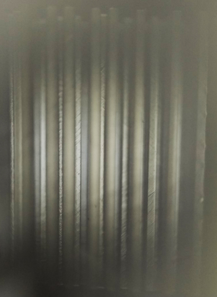
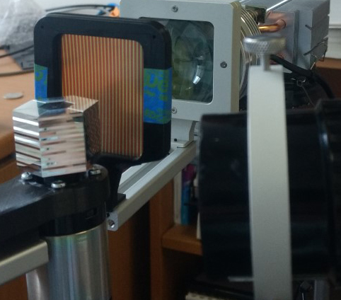
Reflected image on nano-lathe cut mirror facet.
If my mirrored polygon facets rotate too slowly then my eye/brain perceives the previous image frame ‘superimposed’ on to the current projected image frame (disrupting the illusion of movement), if it rotates too quickly then my perception is unable to decipher the detail of the moving image. Max Wertheimer defined this phenomenon in 1912, which interestingly pre-dates Reynaud’s optical devices. As further evidence of Reynaud’s ingenuity, he understood both this perceptual effect as well as the persistence of vision, a phenomenon which is sometimes erroneously attributed to how we see moving images. Reynaud’s systems were of course hand-cranked and so the human performer manually rotated the images frames. With my optical system I’m more interested in having the device as the performer or (magical conjurer of optical tricks!) and engaging the viewer with this exposed device as well as the projected moving images. This is the reason for my use of motors.
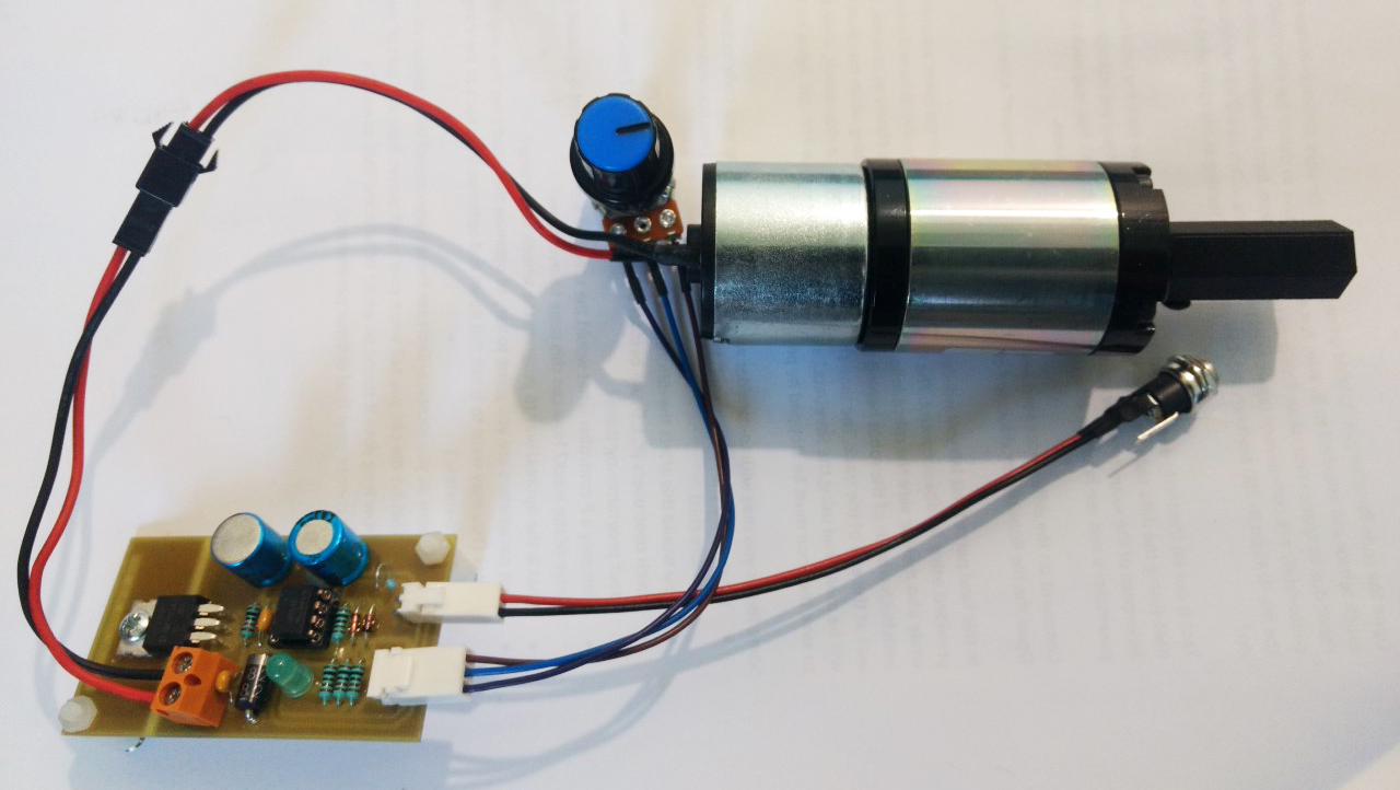
The rotational speed and smoothness of the motor is crucial therefore to generate a seamless effect of movement in the projected image. With Dennis Gibson‘s and Luke Materne‘s help and expertise, we sourced an industrial grade geared DC motor that could handle very slow speeds and still have sufficient torque to rotate the polygon.
DC geared motor connected to PCB and power supply. When everything is tested and operational within the optical system, I will fabricate a translucent casing for the motor and PCB, allowing the viewer to see the entire mechanism of the device.
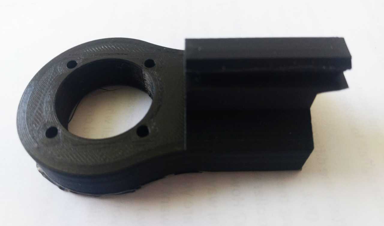
Dennis also printed and built a PCB giving me extra control over fast-starting, altering the speed so I can test for the optimal speed in relation to the perception of the moving image, as well as the direction of the motor. I’m currently 3D-printing the collar mount so I can place the motor and polygon into the optical system and start testing the projected moving image. I made this collar with quite chunky specs becasue the motor is 300g in weight, quite a heavy motor for its relatively small size.