After testing different motors, (both stepper and DC) at different speeds to rotate the polygon, I couldn’t find an optimal speed to generate the illusion of movement in the moving image. I spent time researching why this might be the case and then I realised that it wasn’t only dependent upon rotational speed and the viewer’s perception of vision (as I wrote about in a previous post). It was also depended upon the relation between the speed of the polygon and the angle that each facet rotates within the optical system.
My previous work with mirrored polygons and moving images had used 48 frames. However for the ANAT project, because the creation of the mirrored facets was much more complex (patterned as opposed to flat facets), I’d been working with six-sided polygons to learn the nano-lathe and work out the optics. Therefore every facet is required to rotate 60 degrees to position itself in front of the optical system. I thought that increasing the rotational speed would solve this issue. However, after testing the polygon with a faster motor speed, I found a threshold for rotational speed and the moving image becomes an indecipherable blur!
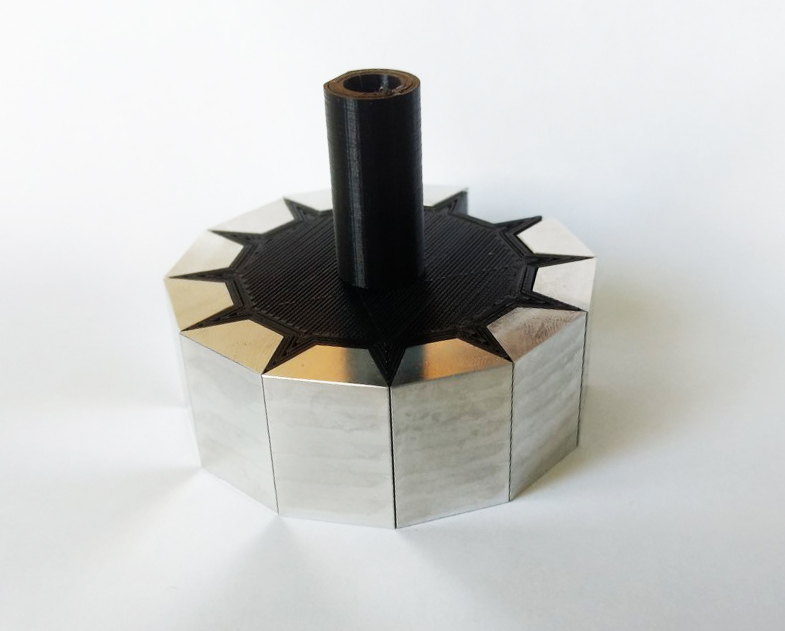
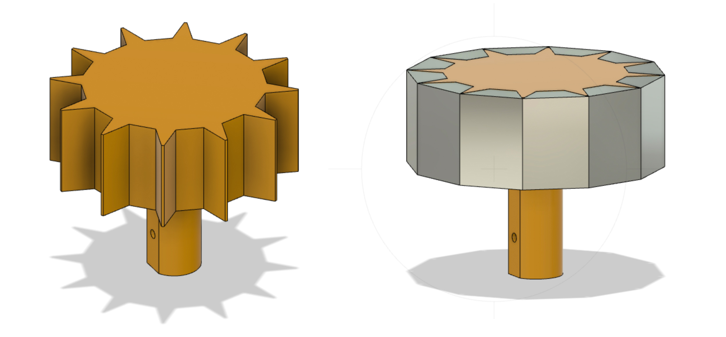
I decided to increase the number of facets on the polygon – to reduce the angle of rotation and investigate if the ratio of the angle of rotation to the rotational speed is critical to the perception of movement for the viewer. I used the last of the blanks Neil Devlin had fabricated and I designed and 3D-printed a jig to connect to the motor shaft and hold the aluminium facets.
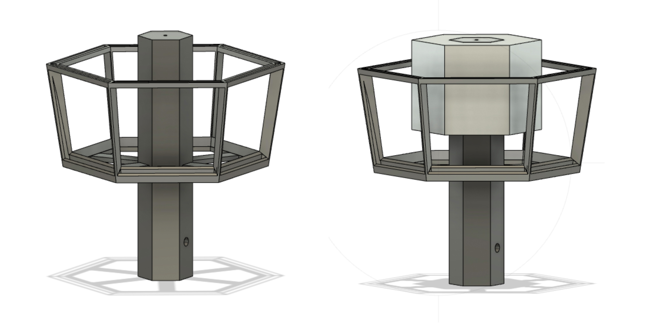
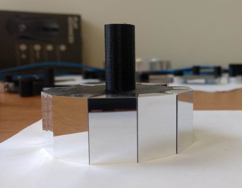
Testing with plane mirrors rather than cut mirrors
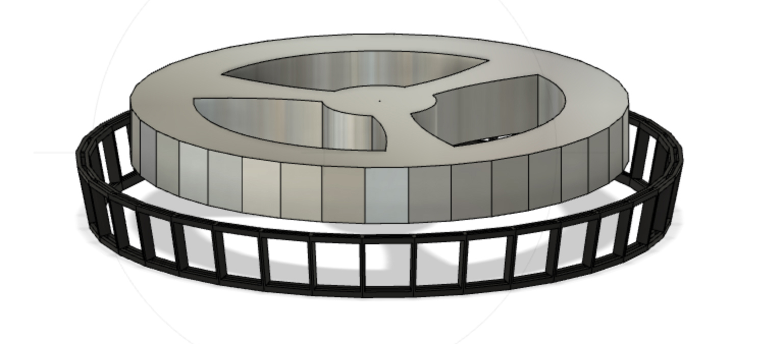
Because each facet takes approximately 12 hours to cut, I decided to use a faster way of working out the minimum number of facets. This method uses multiple image frames as well as mirrored facets. Moving from 6 to 12, 24 and 36 frames I modelled up a series of mirrored polygons and image frames holders which would rotate around a single shaft to generate the moving image. This is based on the 19th century technique used by Charles-Émile Reynaud (see previous posts) and which helped form my idea of using multiple mirror facets and a single image frame.

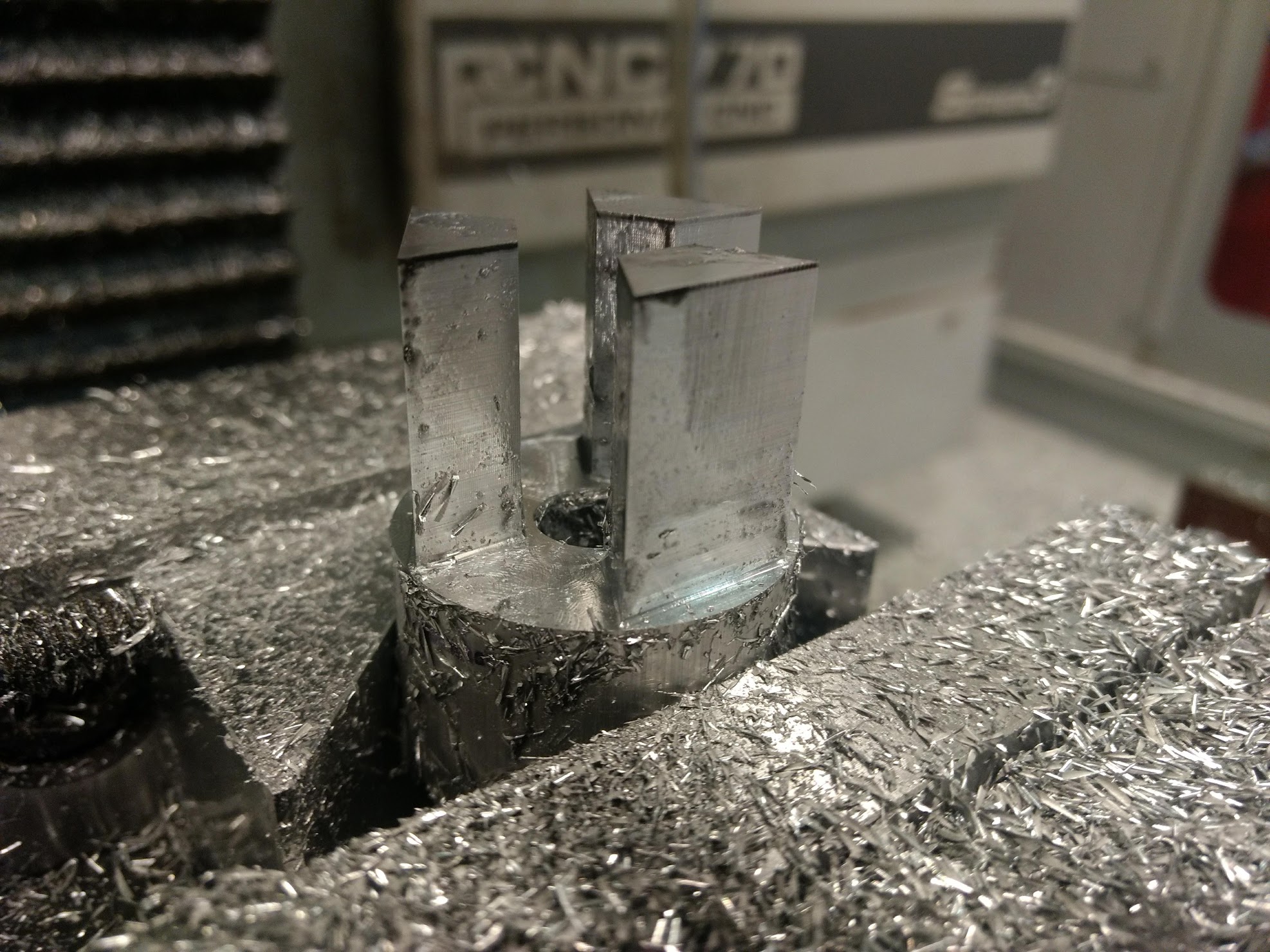
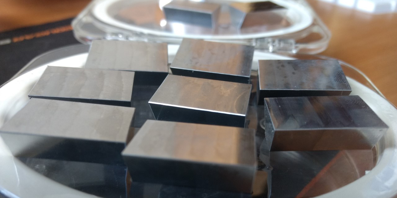
I polished as many facets as I could and then realised that I would need to make many more in order to test the moving image.
I wanted to learn how to make them using the C ‘n C Tormac mill in the Maker Space. Jordan Haddrick, all round technical guru from the Maker Space inducted me on the machine. Like the nano-lathe, its a steep learning curve for me as I enter back into the Cartesian world of x, y and z planes! Jordan was very generous with his time assisting in the first production run of the facets and soon I hope to be up and running independently on the mill.