Now that I’ve got the hang of the nano-lathe and have been cutting the remainder of the polygon facets, I needed to venture into the world of controlled motor speeds to test the mirror facets in the optical system.
Rotating the polygon facets at very slow speeds has turned out be more complicated that I thought, especially as I’m using a small sale motor. I’ve been working on solutions with Dennis Gibson and Luke Materne in the Electronics Unit of the School. We’ve been building and testing various motor speeds using small steppers, PCBs and Arduino and then moving onto geared DC motors. So why is a slow rotational speed so imperative to my optical moving image system?
The perceptual optics of the systems I’m experimenting with require very slow speeds to allow the viewer register an image that is both in motion and focused. What I found, to my surprise, is that my systems require a speed less than 12 frames per second, which is normally the threshold speed to perceive image frames in motion. When this rate drops below this rate, the human vision system perceives the image frames individually. I’m very curious to test this out with my nano-lathe cut parts, where instead of using multiple image frames, I’m using multiple mirror facets, which in terms of optics, should function in the same way.
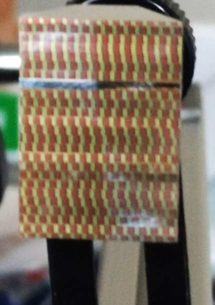
Part of my fascination with Emile Reynaud’s 19th century praxinoscope and elaborate Théâtre Optique system was his use of optical mechanics to overcome his lack of shutter or maltese cross mechanism. These interventions temporarily pause the image frame (either perceptually or mechanically) in front of the objective lens. I tested Reynaud’s Théâtre Optique system without the mirrored polygon, where I used only the translucent image frames. The projected moving image was a blurry mess of incomprehensible images!
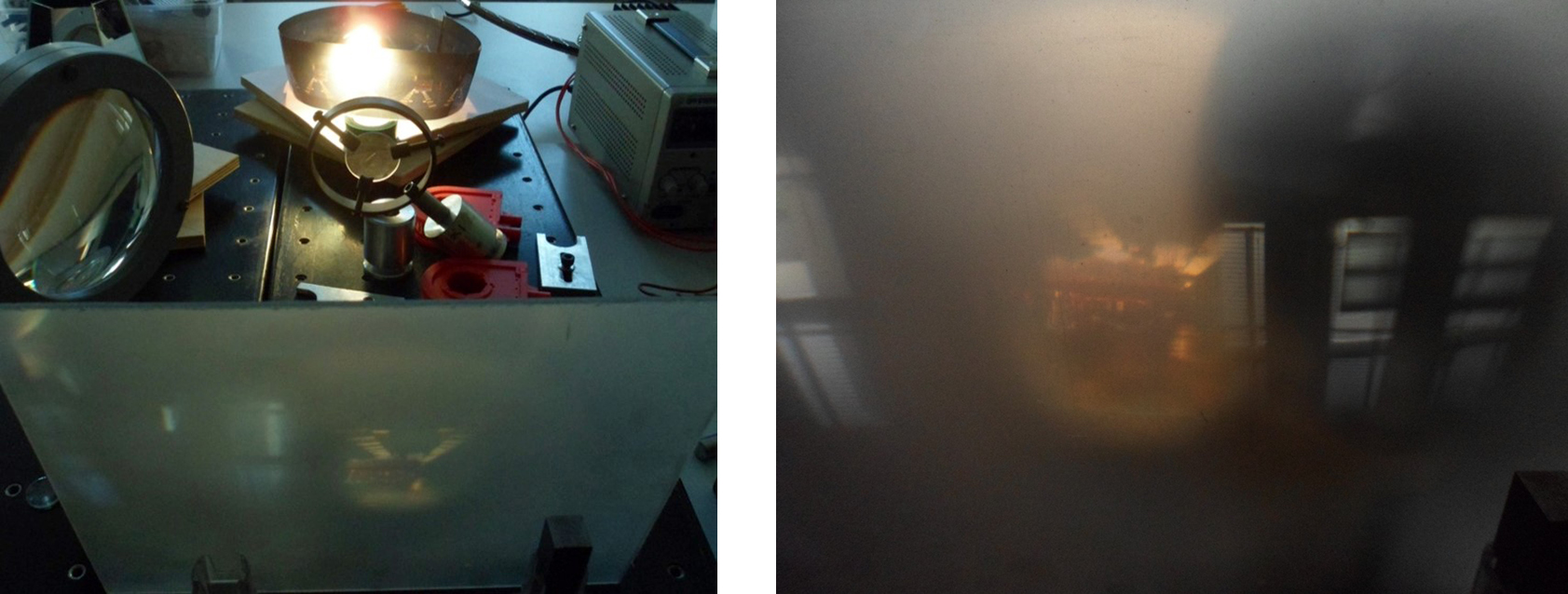
The flat facets of my polygon system (based on Reynaud’s) create a kind of ‘optical pause’ in front of the objective lens and so each frame remains in focus while in continuous motion. But this effect is due to more than the apparatus itself. It is also due to the phi phenomenon that occurs as part of our perceptual system – the optical illusion of perceiving a series of still images as being in continuous motion, when viewed in sufficiently rapid succession.
If my mirrored polygon facets rotate too slowly then my eye/brain perceives the previous image frame ‘superimposed’ on to the current projected image frame (disrupting the illusion of movement), if it rotates too quickly then my perception is unable to decipher the detail of the moving image. Max Wertheimer defined this phenomenon in 1912, which interestingly pre-dates Reynaud’s optical devices. As further evidence of Reynaud’s ingenuity, he understood both this perceptual effect as well as the persistence of vision, a phenomenon which is sometimes erroneously attributed to how we see moving images. Reynaud’s systems were of course hand-cranked and so the human performer manually rotated the images frames. With my optical system I’m more interested in having the device as the performer or (magical conjurer of optical tricks!) and engaging the viewer with this exposed device as well as the projected moving images. This is the reason for my use of motors.
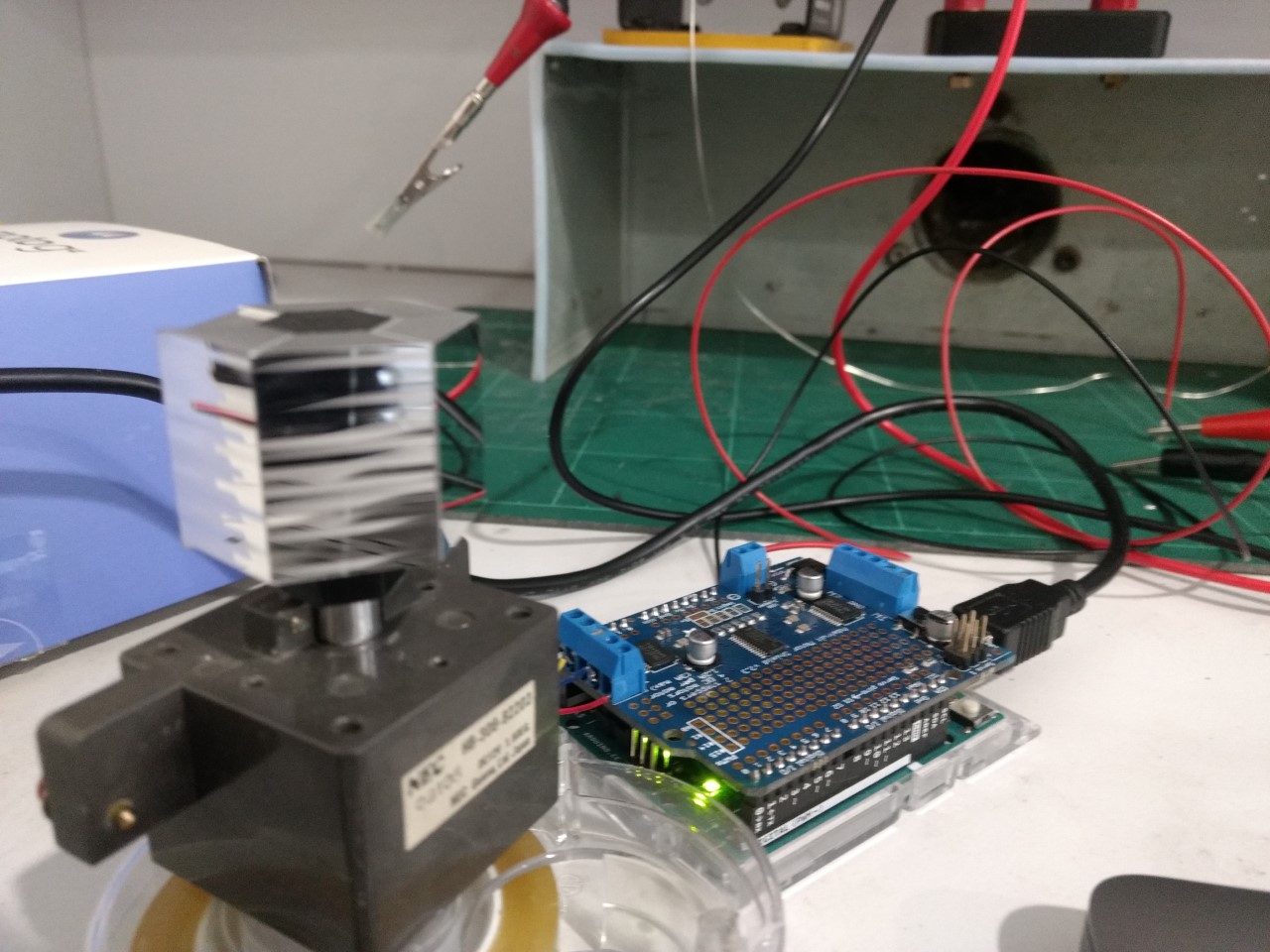
The rotational speed and smoothness of the motor is crucial therefore to generate a seamless effect of movement in the projected image. With Dennis Gibson‘s and Luke Materne‘s help and expertise, we sourced an industrial grade geared DC motor that could handle very slow speeds and still have sufficient torque to rotate the polygon.
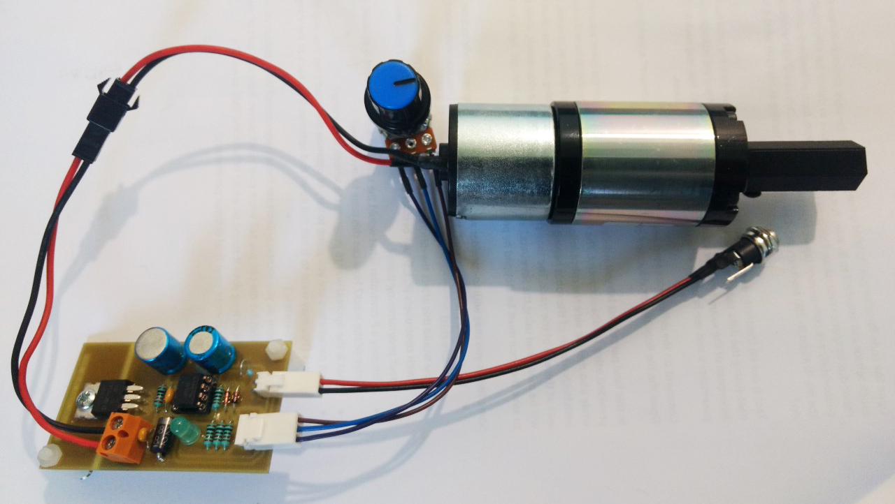
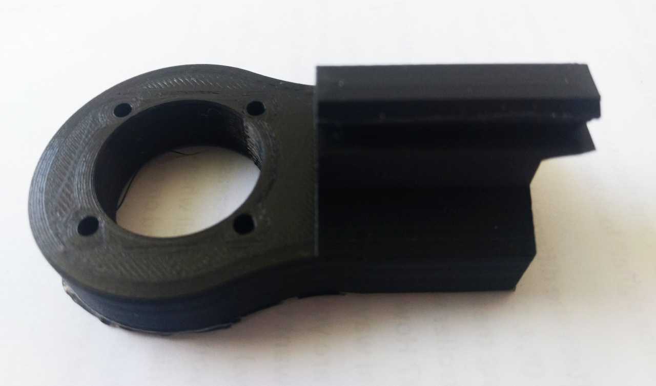
Dennis also printed and built a PCB giving me extra control over fast-starting, altering the speed so I can test for the optimal speed in relation to the perception of the moving image, as well as the direction of the motor. I’m currently 3D-printing the collar mount so I can place the motor and polygon into the optical system and start testing the projected moving image. I made this collar with quite chunky specs becasue the motor is 300g in weight, quite a heavy motor for its relatively small size.