Vertical and Horizontal Stripes
This week I was off the nano-lathe and focused instead on creating images to match the cut planes of the mirror facets. I put both of these into my optical system for testing and figured out that there would be lots of incremental changes to make. I began by printing a series of small scale translucent images to allow the light travel through the image and onto the mirror plane.
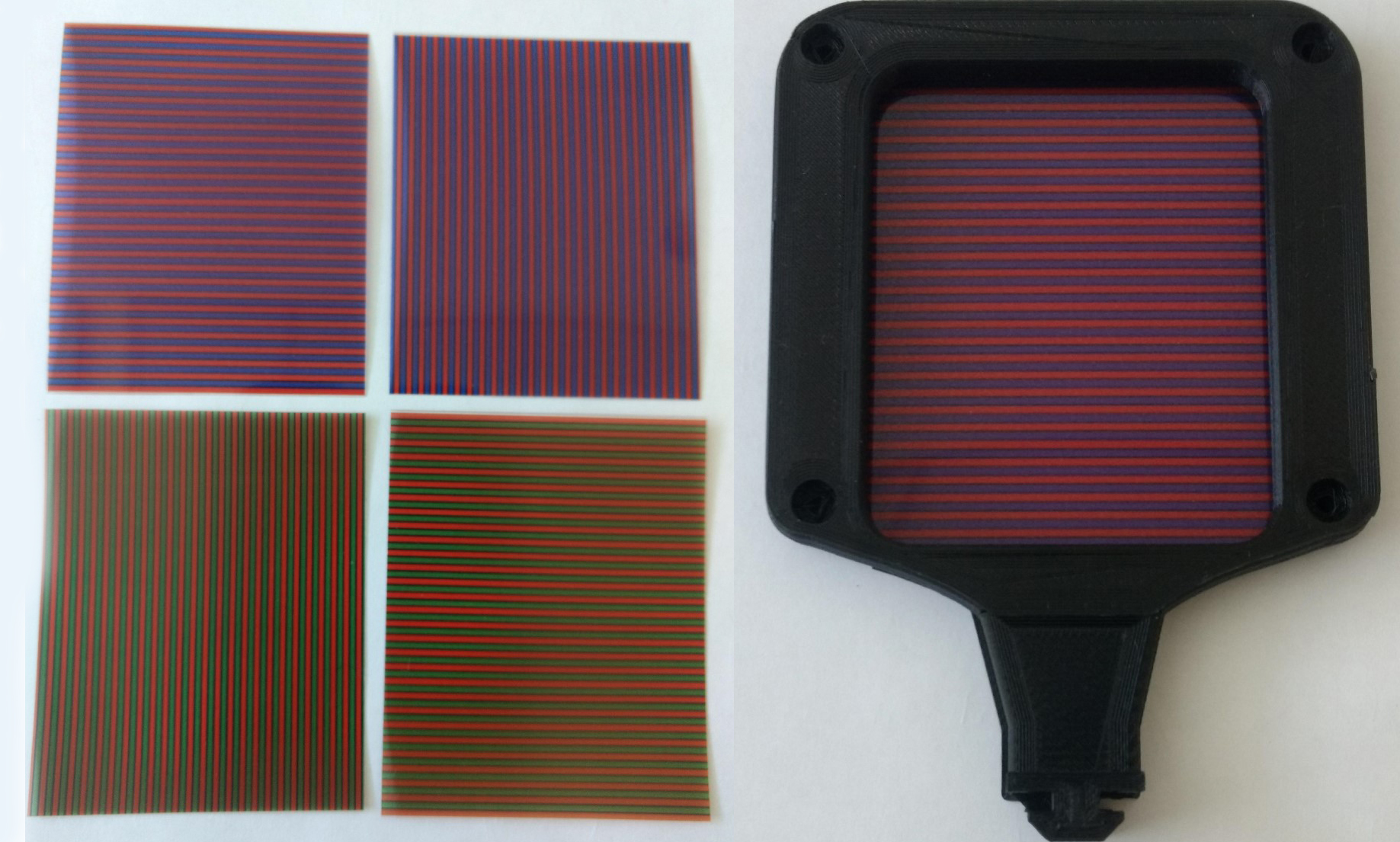
I created both vertically and horizontally striped images to reflect at 90 degrees to the cut mirror plane. That is, for the mirror with vertical cuts, I reflected/projected a horizontal stripe image and vice versa. This allows me to see how much the depth of cut bends the light and if my next program for the nano-lathe requires deeper cuts. These striped images are just for optical testing, when I work out how much the light bends I will create a series of images and matching mirrors.
Within the images I added a fine black stroke line in between each coloured stripe. This allows my eye to pick up the change in direction of the light (stripe) more easily – a trick I picked up from the 19th century artist-engineer Charles-Émile Reynaud! He used a black background in his image frames so that the viewer could more easily perceive the change in the characters in the foreground.
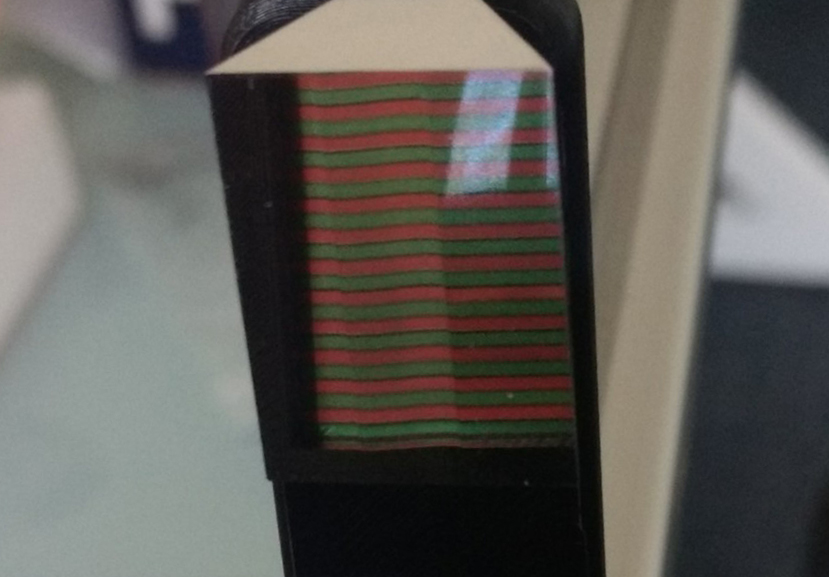
Image and mirror holders
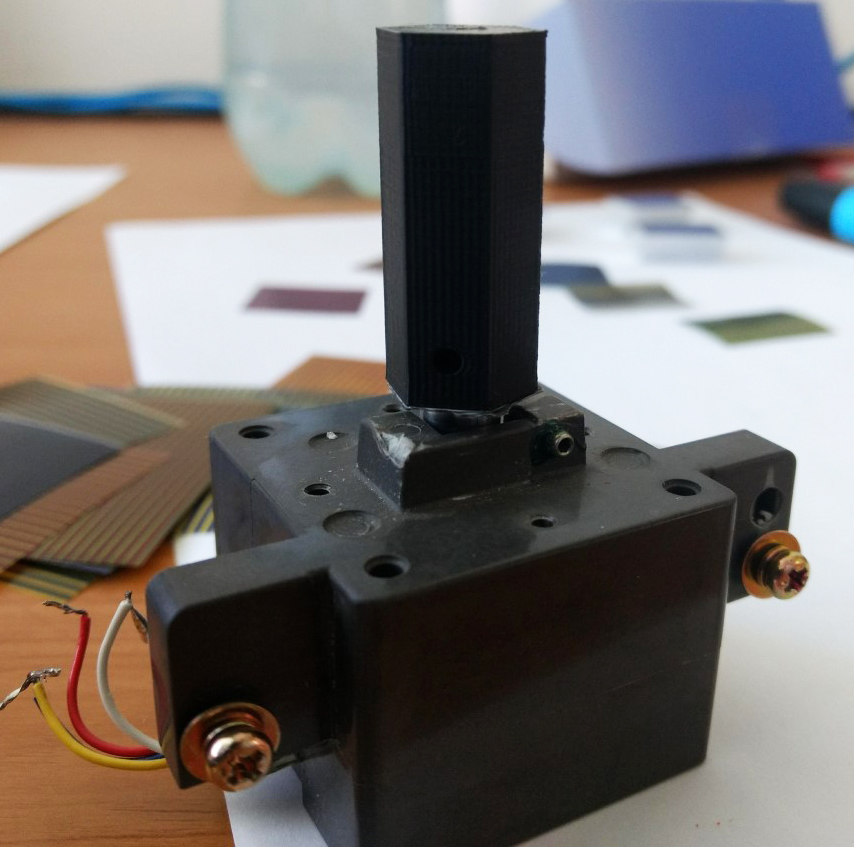
After preparing the images, I modelled up and 3D-printed some image holders so I could control their position in the optical system. Originally I thought that the image size needed to be exactly the same as the mirror, but when I tested this, it turned out that the image frame needs to be significantly larger than the mirror to compensate for the distance between the image-object and the surface of the mirror.
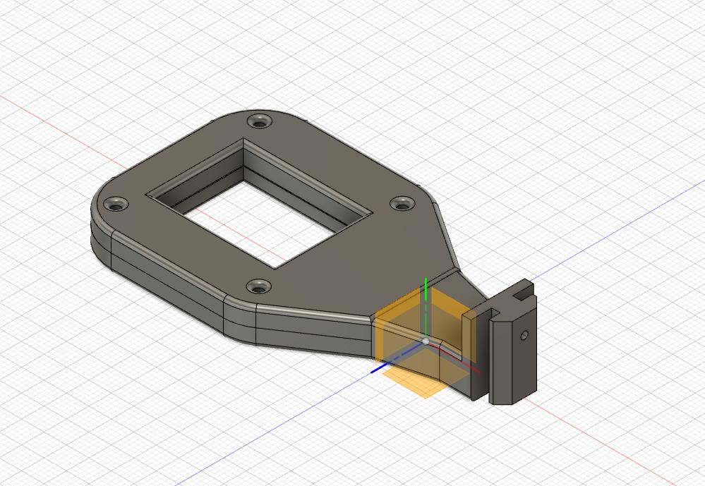
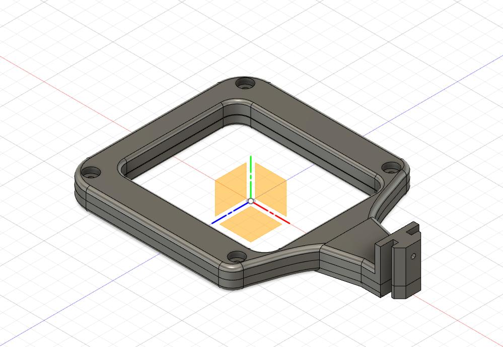
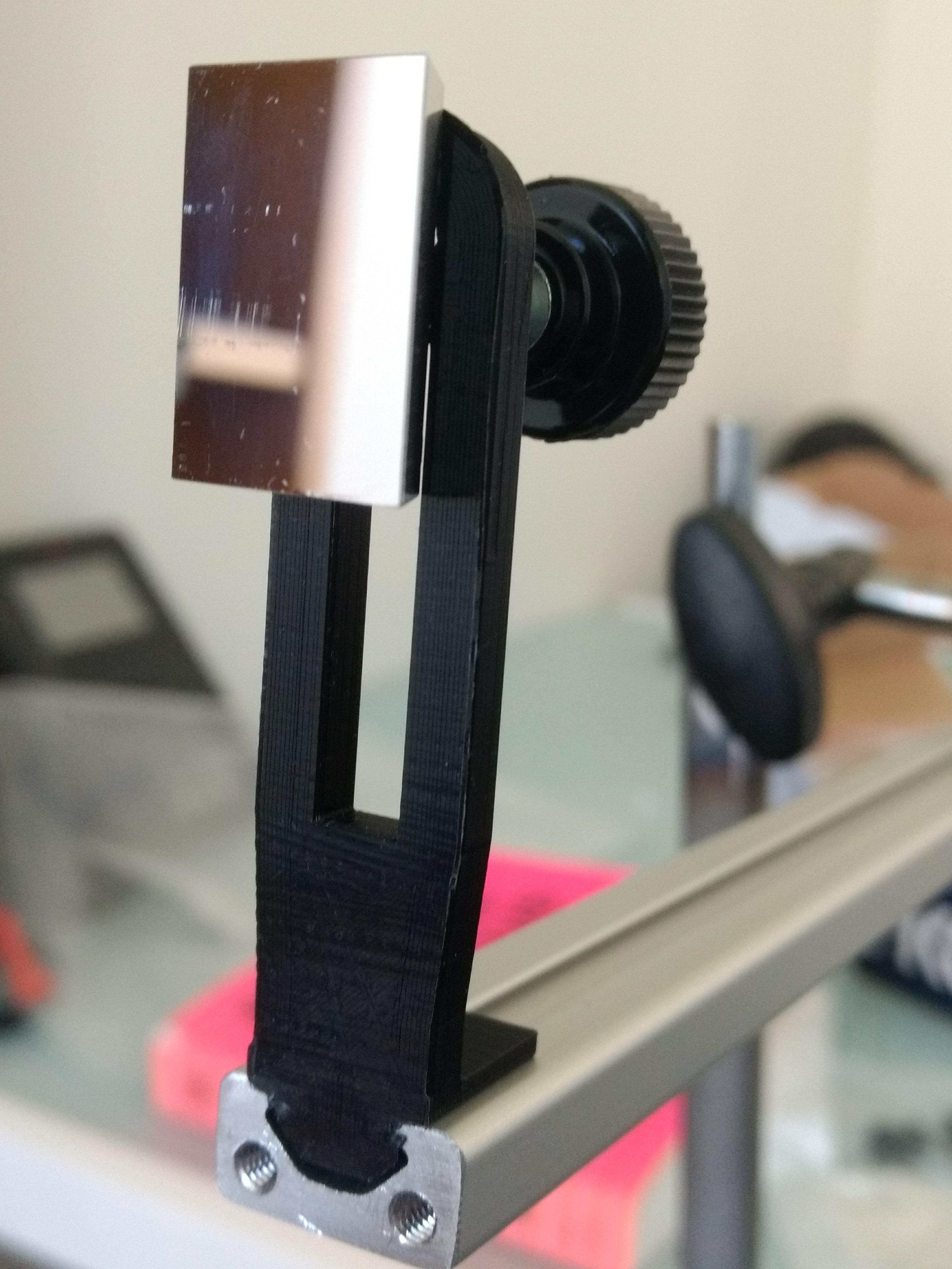
Before placing the facets onto the polygon gig, I needed to test a single mirror facet in my optical system and therefore modelled up a small holder for the mirror.
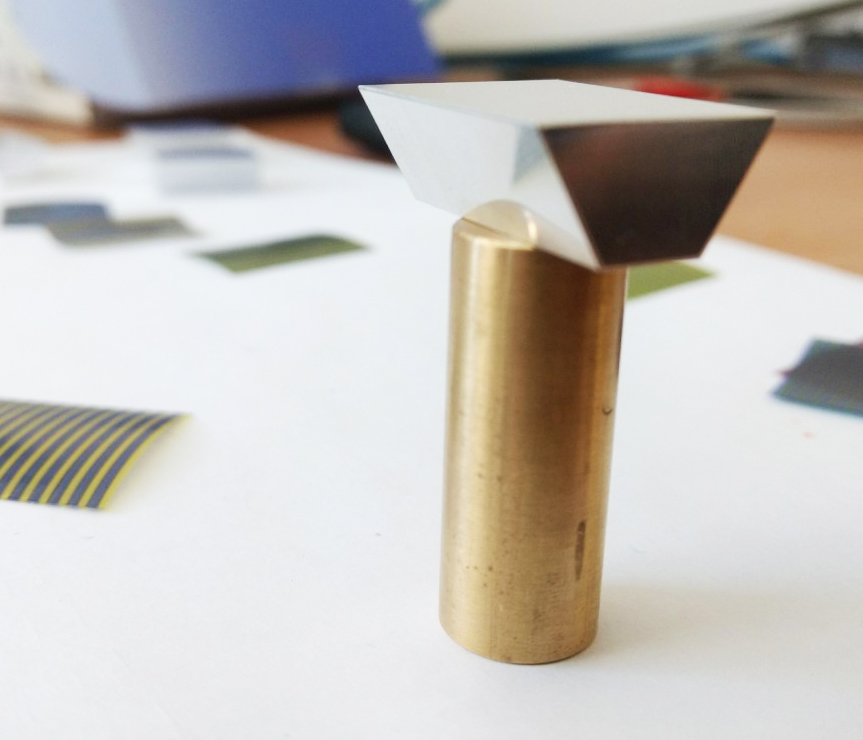
At the same time Tom Cave from the School of Physics Workshop make a brass gig allowing me to easily attach the aluminium facets onto a holder for cutting. This will make centring the placement of the facet on the spindle much easier – for when I’m back cutting again next week on the lathe!
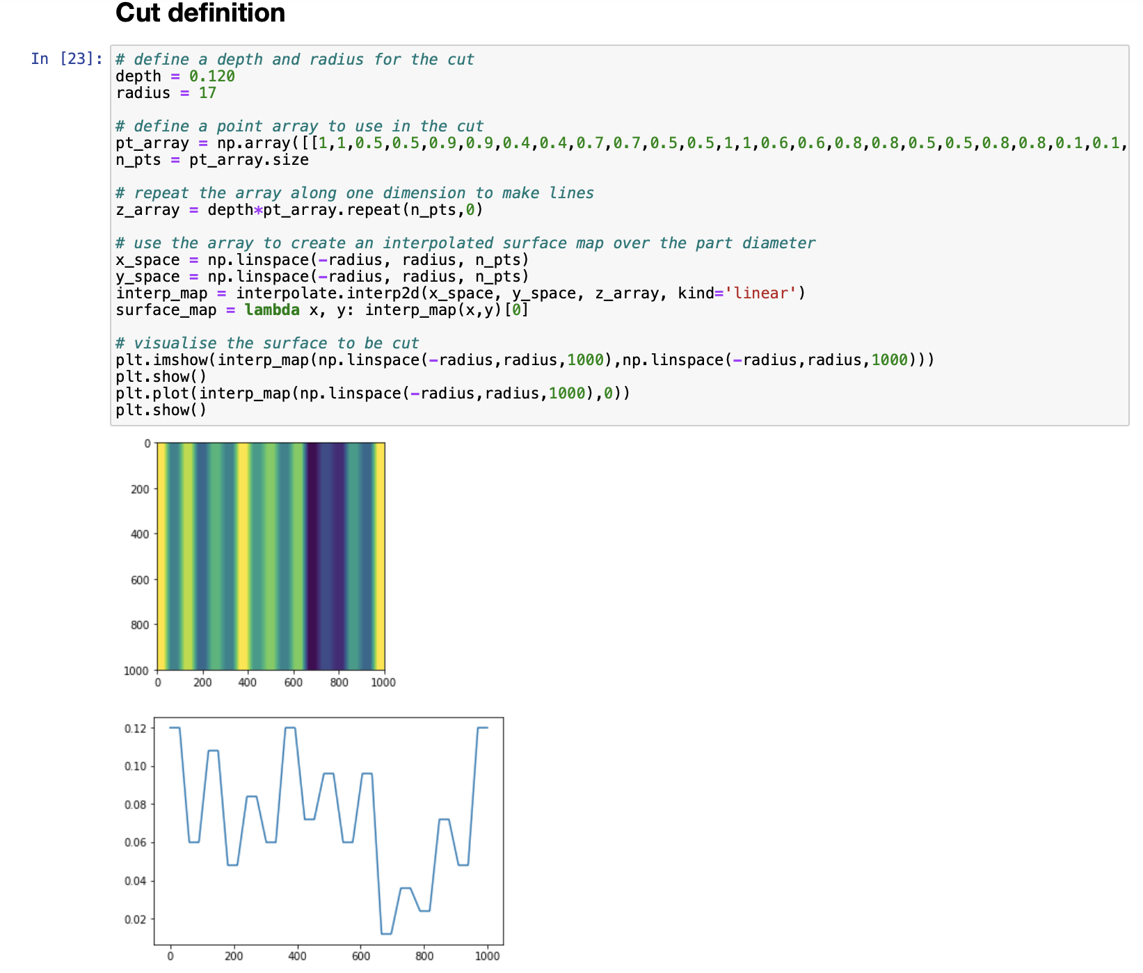
Geoff and I have been working on a python script that we will use next week once back on the machine. We’ve been working towards achieving more stepped and deeper cuts on the aluminium facets, to see if this changes the reflected image more dramatically.