Zooming in and out – from nano scale to millimetres
Over the last few weeks I have been on a steep learning curve, venturing into the world of nano fabrication. It’s been quite a disorienting experience adapting my visual thinking to a Cartesian reference system to accommodate the different axes of the nano-lathe and understand how the g-code relates to the physical behaviour of the machine.
The constant moving back and forth between a such precision machine and 3D printers has forced me to continuously shift my focus. The shiny mirrored parts I’m making on the nano-lathe require my gaze to zoom in beyond what I can see without the aid of a powerful magnification lens. When I jump back onto the 3D printers, I feel my gaze zooming back out again and a millimetre now seems extraordinarily large! This shift in perception has made me think of a quantum physicist or astronomer, constantly oscillating between the ‘zoomed-in’ world of minuscule or faraway objects and the ‘zoomed-out’ world of everyday life.
What I’ve been testing, exploring, making
Cutting the mirrored facets
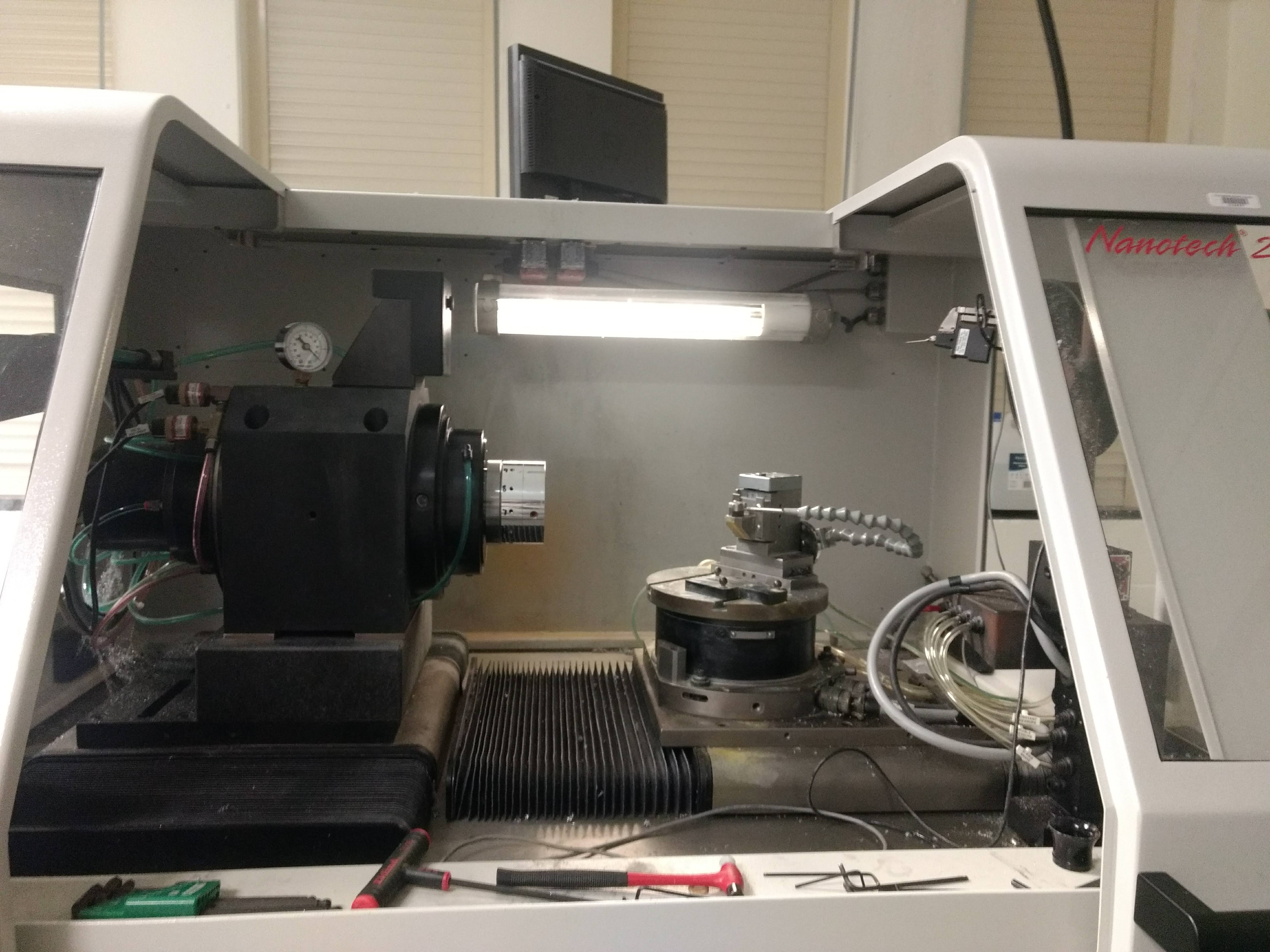
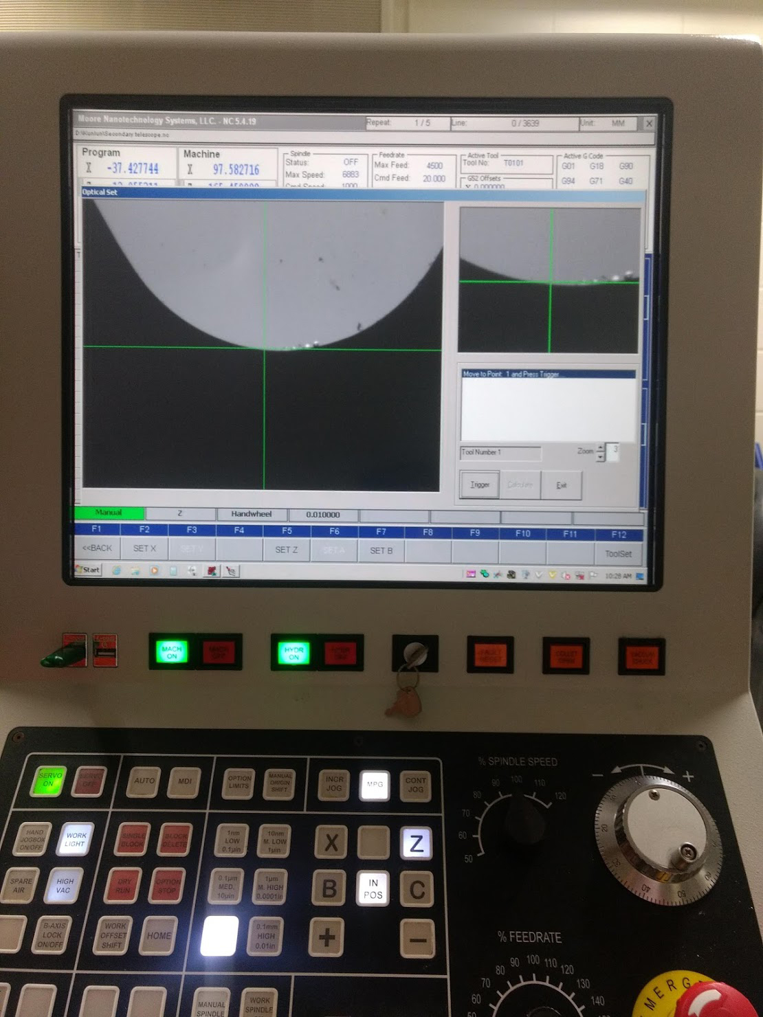
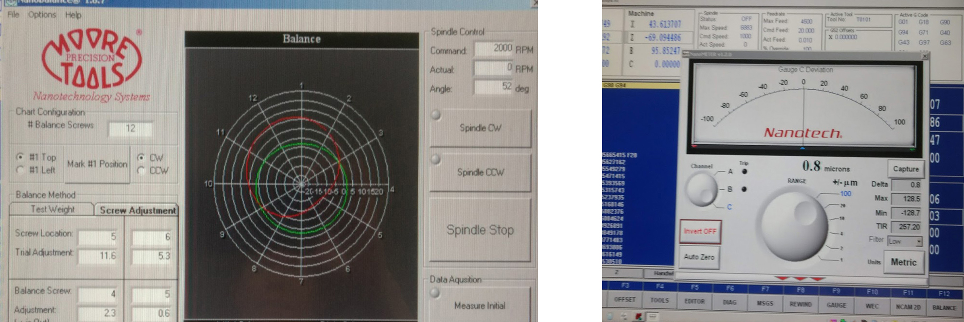
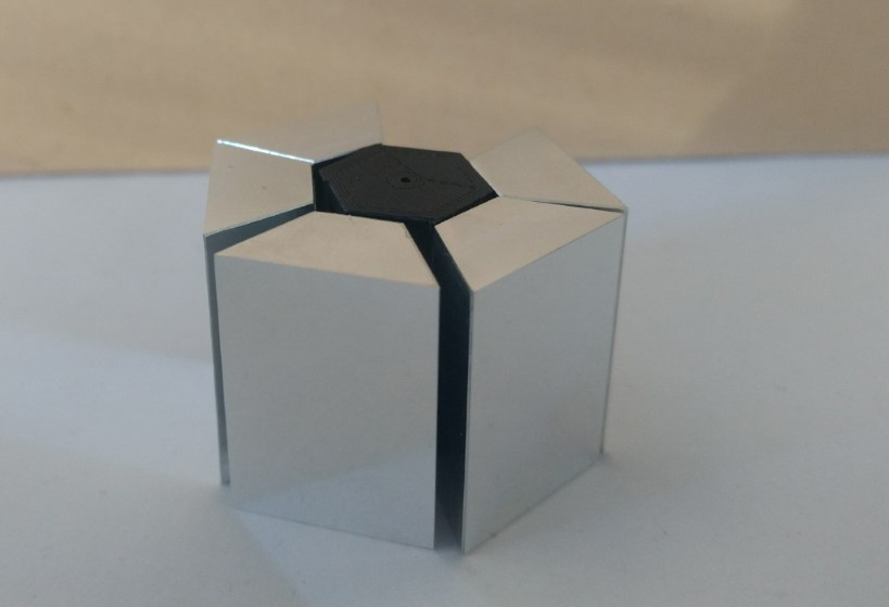
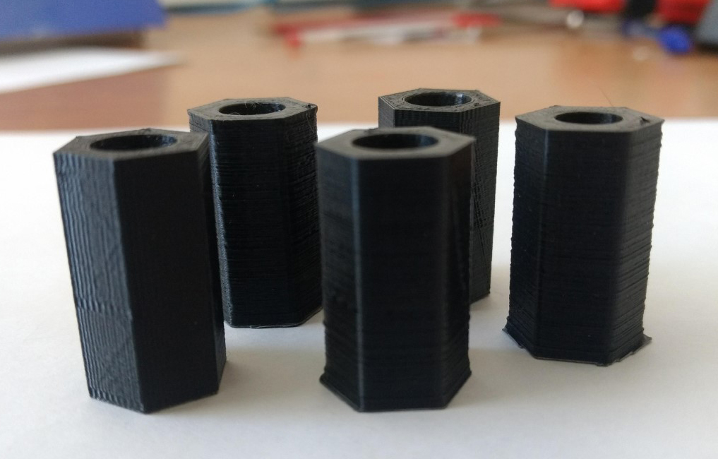
My collaborator Geoff Campbell has been patiently showing me the steps of the nano-lathe and there are many! After learning how to zero the various axis of the machine using a magnifying camera, probe and balancing system, I began facing components for a small 6-sided polygon, which I’ll place in one of my optical systems for testing – to see how these facets affect my image.
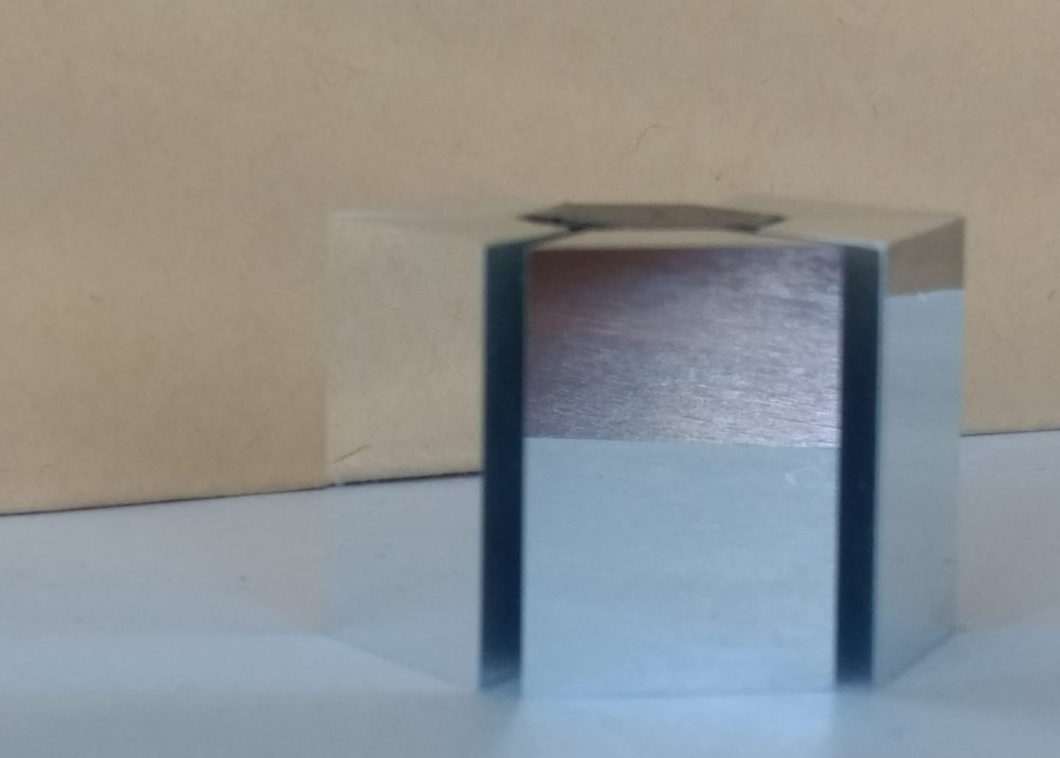
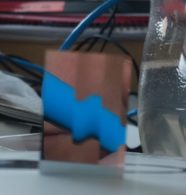
Neil Devlin cut a series of blanks for me to use on the nano-lathe and after facing them I’ve now begun to cut splines (patterns) into them. These patterns form the outer surface of the polygon and determine how the image-light, which travels through the image frame, is reflected off the mirrored surface and into the objective lens. By controlling the depth of cut to the mirror plane, the facets shift certain parts of the image. The images below with the wavy blue lines demonstrate how much the cut mirror surface changes the direction of the light. The wavy blue line is the reflection of a (very straight!) blue highlighter pen.
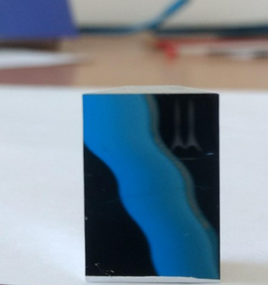
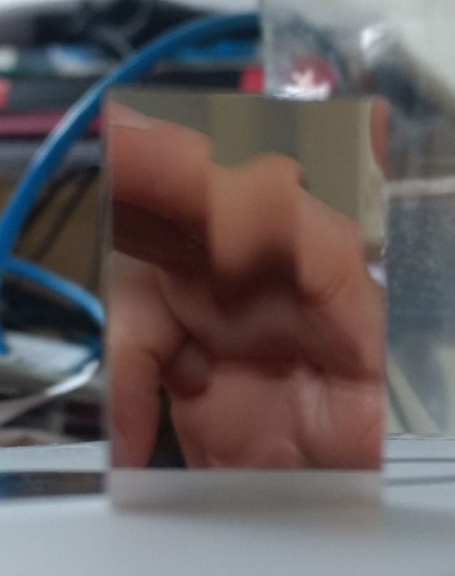
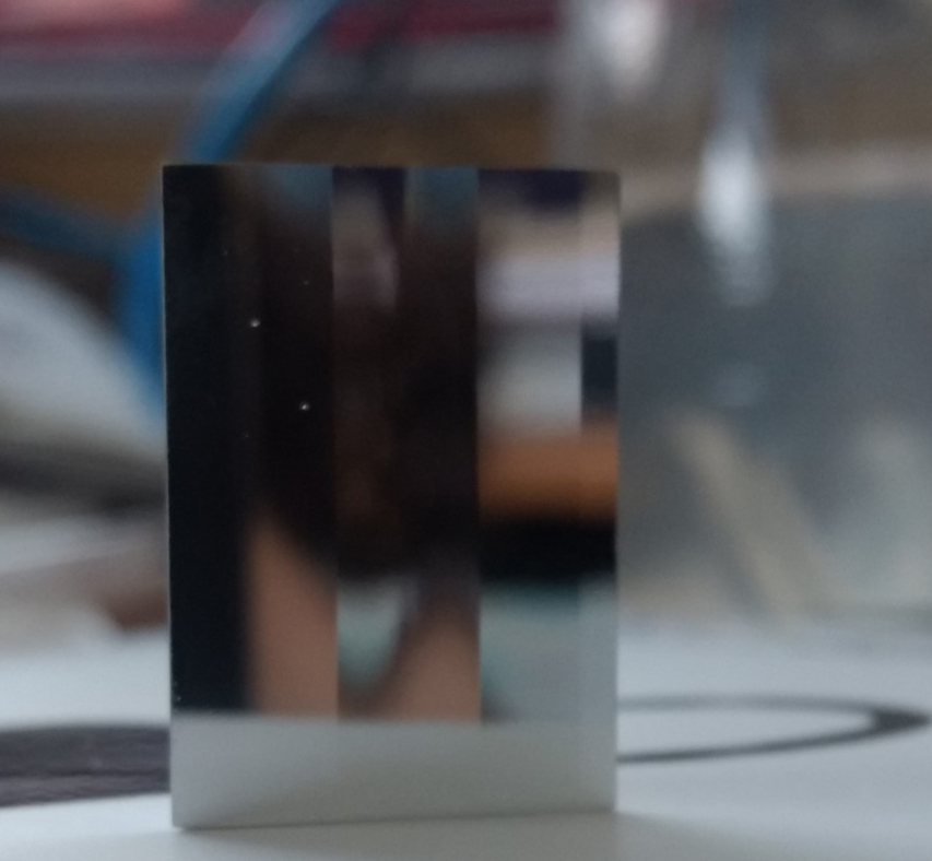
This visual ‘relocation’ of certain areas of the reflected image will enable me to control the movement within the projected image, when placed into my optical system. We’ll be producing lots of iterations of these facets, experimenting with how the light ‘bends’ specific images and consequently creates the illusion of movement in the projected image. As the mirror cuts are so shallow on the lathe, I’m also exploring with Geoff how to calculate the distances required from the image source to the mirror facet to the objective lens and viewer. The next step is to play with how each cut on the mirrored facet bends specific sections of the image, so we can develop a sequence of cuts for the polygon facets.
Rotating the mirrored facets
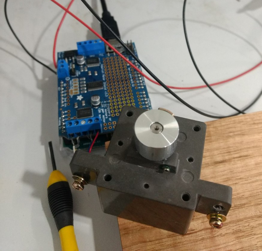
I’m assembling the polygon components around a single rotating shaft, connected to a small stepper motor, controlled by a driver and some simple Arduino code. I 3D printed a set of gigs which will hold the individual mirror facets and sit on top of the motor’s shaft collar. As the motor rotates the polygon within the optical system, each uniquely patterned facet will refract the reflected image-light differently to create the illusion of movement in the projected image.
Rotational speed is important for the perception of movement in the projected image. So far I have only been able to set the motor to rotate as slowly as 10 RPM, so I might need to add some gears to slow it down further. Luke Materne from the Electronics Unit at the Research School of Physics has been helping me with this. More things to learn!
Cutting Splines into the facets
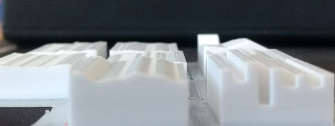 To begin a conversation with Geoff about the mirror cuts, I 3D modelled and printed some surface profiles. Understanding now how the nano-lathe works has modified my thinking about how to make the mirrored facets. Geoff wrote a python script to approximate the spline into a series of points and then turned this into g-code for the nano-lathe. The machine also cuts very slowly, for example a facet of 18mm x 25mm takes about 4 hours to cut about 120 microns (0.12mm).
Each cut has to be parsed several times with rough and finish cuts of different depths. It’s been really interesting to discover that the cut in the mirrored facet doesn’t have to be very deep. If it is combined with the correct focal length lens (that is, the distances from the mirrored facet to the objective lens and projected image) one’s visual perception still picks up the refraction (or change in the image).
Conversations with Geoff
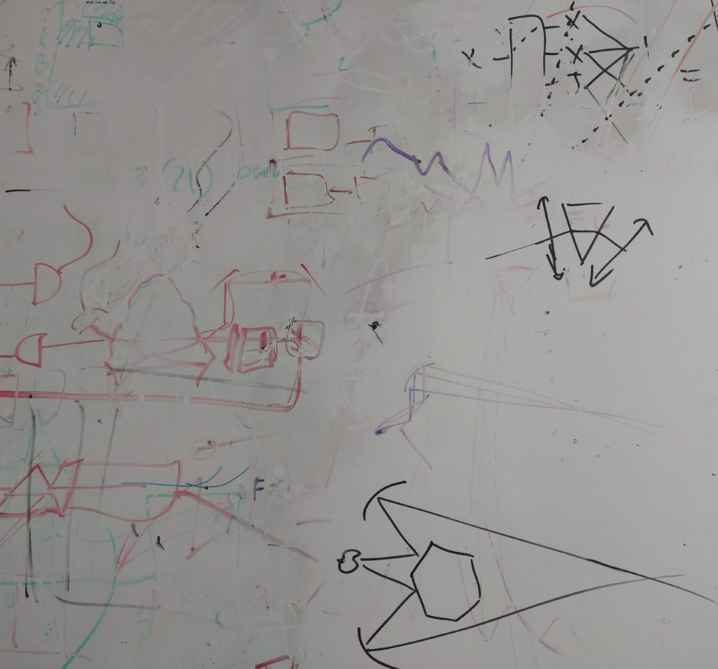
There’s been lots of 3-way conversations been Geoff, myself and the whiteboard! As well as mirrors, we’ve started discussing how we can use the nano-lathe to cut some lenses using optical grade acrylic. We’ve also begun a dialogue about splitting up our optical system to have 2 mirrored polygons running on perpendicular axis. This will double the effect of the apparent movement in the projected image.
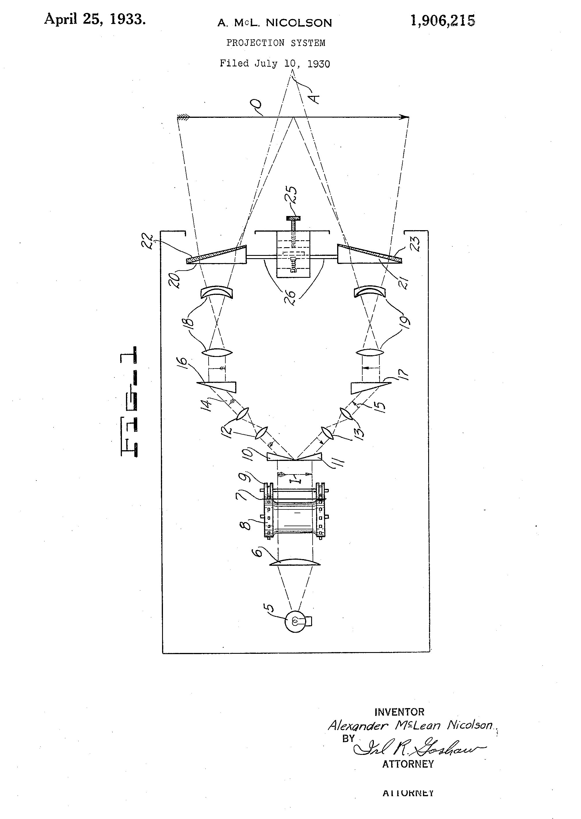
To explore this further I’ve been looking at Charles Wheatstone’s 19th century stereograph system, where he uses 2 image sources and angled mirrors to create a single image with a depth of field. I’ve also been exploring lots of historical optical device patents to look at different configurations for optically recombining the 2 separate images into a single projected image. The important difference between our system and Wheatstone’s stereograph system, is that our system only uses a single image source.