While waiting for the new DC geared-motor components to arrive, I began conversations with Geoff about cutting some lenses on the lathe – a very exciting prospect for me, with my glass-making background!
Machinist Neil Devlin made some lens blanks from the optical acrylic I sourced and a gig to hold them on the lathe. The gig was specifically designed to fit the lathe spindle and allow me to flip the lens to cut the other side without touching the newly polished surface. It’s been a great learning experience working with Neil. When I provide him with models and drawings, we have follow-up conversations to refine any oddities in the designs and functions of the components. As a maker, I never cease to be amazed by his ingenuity and skill as a machinist engineer.
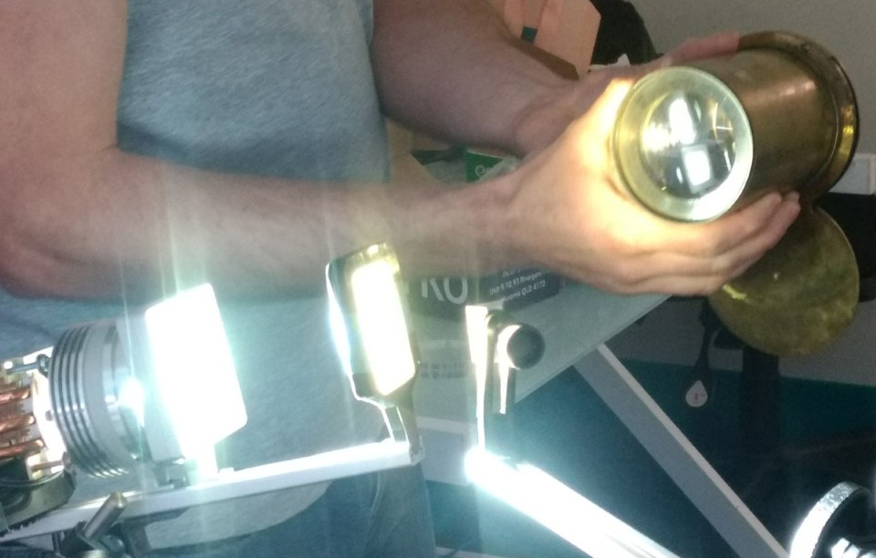
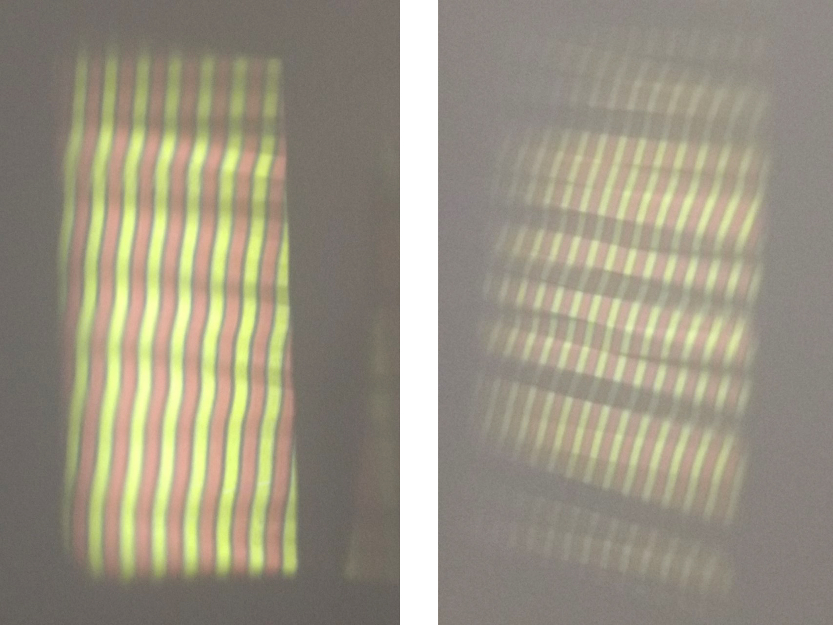
Geoff and myself then worked out the focal lengths and curvatures of the lenses. We knew that we would need at least one lens with a long focal length (to project and magnify the image from the polygon facets). This would need to be a thin lens with a large radial curve. I set up the components in the optical system (LED, condensers, image frame, mirror facets, objective lens) to roughly calculate the distances between the image frame, the mirror and the objective lens and the lens and the projected image. It was tricky calculating each distance, but by trial and error, moving the position of each component systematically, we finally got our projected image.
The mirror needed to be very close to the image frame. However because the mirror facets will be in motion (as part of the slow moving polygon), it’s better that the polygon is located at a certain distance from the image source (to avoid collision with the image frame). We decided therefore to use an extra short focal length lens to image the reflected image first (which would be at the specific location of the polygon facet) and then project that image into our objective lens to be magnified and projected. This requires a relatively thick lens to refract, demagnify and focus the light rays at a short distance from the centre axis of the lens.
New Collaborator
To work out how to specifically design the curves and thicknesses of the lenses and to avoid any form of chromatic aberration, we used an optical software Zeemax. This however was outside of Geoff’s area of expertise. I’m delighted that Dr Noelia Martinez Rey, a post-doctoral fellow who specialises in adaptive optical systems at the Research School of Astronomy and Astrophysics is keen to come on board as a collaborator. She will help Geoff and myself design the lenses for the polygon image system. Noelia is an expert in Zeemax and will use it to design both the single short focal length lens and the composite objective lenses. For the latter she will design a single lens rather than the usual 2- 3 lenses usually required for objective composites. We will fabricate her designs using the nano-lathe. I am very excited to see these lens outcomes!