MirrorMirror has emerged from wide ranging interests in historical and contemporary wonder and the projected image and its generating device. This introductory post will provide some context for my project – how I came to work with optical image systems as mechanisms for generating wonder and how I will use my ANAT Synapse Artist Residency to begin prototyping a new image system in collaboration with quantum optical physicist Dr Geoff Campbell at the ANU Research School of Physics (RSP). The title of this project alludes to the reflective properties of mirror being explored during the project, but it also references the project’s working process, whereby Geoff and myself will share, discover and learn from our collaborative endeavour.
Projected Image-Light
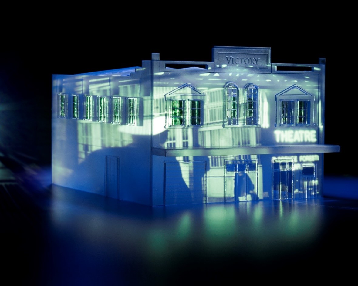 After several years of working with miniature architectural structures in glass and the moving image, projected image-light had firmly cast its spell on me. I projected video-animations or dreamscapes to wrap around my constructed glass buildings. The glass walls, which once encapsulated spaces full of life, now abandoned and empty, released fleeting memories in the form of nonsensical fragments of image-light. As an object maker, I carefully controlled the translucency of the glass, allowing the image-light to enter into the walls and remain there. I focused on glass as a material substrate with which to hold these fleeting images, rather than as part of the mechanism that generated them.
Then one wintery afternoon I stumbled across an exhibition on the magic lantern at the Cinémathèque Française and realised that the material of glass played another crucial role in the history of projected image making. Not just a material which holds the translucent image, glass was as important as light within the projecting mechanism itself. I began to invert my practice – instead of working with glass to create empty architectural structures with which to hold the fleeting dreamscapes, I explored how glass is optically embedded within the technological device that generates the image. Instead of focusing on objects per se, I started to explore how glass objects function as components within overall image systems. First off, I began investigating lenses and their ability to bend light, which led me down a rabbit hole to natural magic and wonder.
Technological objects and wonder
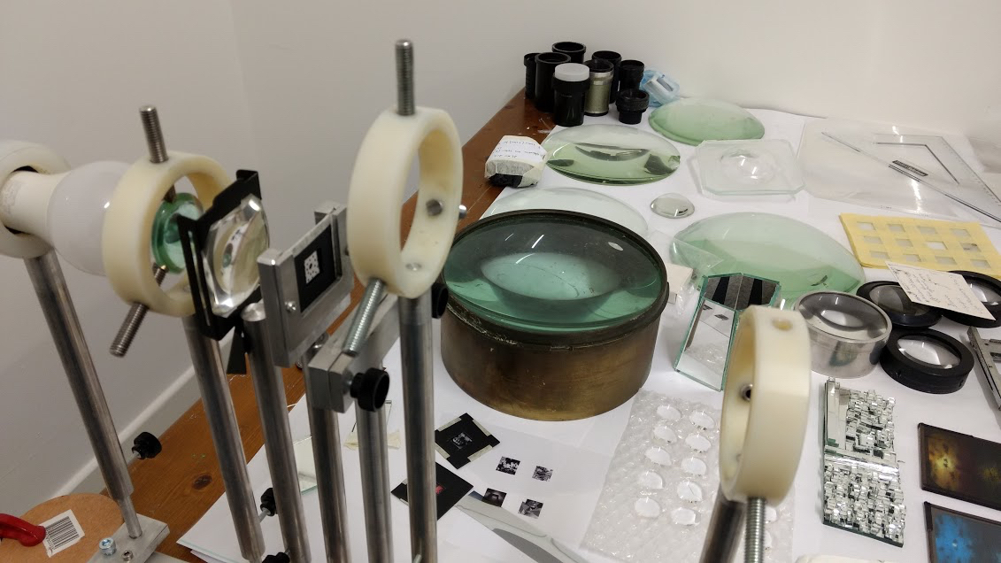 I spent many days in my studio deconstructing various old projection devices, extracting their lenses and light sources. Each time I held up one of the lenses in front of my studio window, the scene from outside was somehow magically transported onto the wall behind me. It seemed unfathomable to me that the material of glass, just by being formed and polished in a particular way and interacting with natural light, could transport an image across my studio, creating its own parallel space-time. Determined to understand the uncanniness of this deceptively simple technology, I looked to the history of lens making and its application.
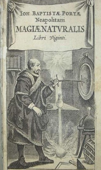 I was amazed by the 17th century natural philosopher and lens maker Christiaan Huygens’ combined mathematical knowledge and material skill in forming telescopic lenses and Rene Descartes’ determined, but ultimately failed quest to build an automated machine to grind and polish a perfect hyperbolic lens. But when I encountered the early optical technologies of preternatural philosopher and natural magician Giovanni Battista Della Porta, (some 80 years before Huygens), a whole new world opened up. The experience of wonder witnessing the uncanny ability of glass to transfer and image of an object across space and time was explicitly used by Della Porta.
Preternatural philosophers from the mid-16th to 17th centuries had an obsession with wonder that was generated from the close observation of nature. They used early optical technologies in the form of lenses and mirrors to see what, until then had remained invisible to the unmediated eye. I was interested in how these optical objects served as illusionary devices to project images of the newly rendered visibilities and incite wonder. For example Della Porta’s contemporary Jean Pena placed a concave mirror (one wonders how precisely formed and polished this object was) inside a camera obscura, projecting images which appeared to hover in the air. Della Porta himself used optical objects to create moving simulacra as part of his performances inside a camera obscura theatre chamber. Reportedly, live performers acted outside the chamber and directly in line with the device’s lens (by 1557 Gerolamo Cardano had already thought to place a lens in a camera obscura). Projected images of their enactments were transported through the device’s aperture onto a wall inside the chamber, where Della Porta’s audience sat wondrously watching the projected images as they unfolded live before them.
I became interested in the interchange between (in)visible technological causes and how in accordance with his practice of natural magic, Della Porta’s audience never saw the source object (the performers) or the device (they were obliviously sitting inside it!), only its detached image. I wanted to create novel optical systems to incite wonder in contemporary audiences, but instead of hiding the apparatus that created my projected images, I would expose the technological mechanism to overtly include it in a system of image, device and viewer.
Charles-Émile Reynaud, optical mechanics and Ghost in the Machine
 During the development of one of my image systems Ghost in the Machine, I came across the 19th century artist-engineer Charles-Émile Reynaud. Reynaud developed a system of optical mechanics first with his praxinoscope and later in his more elaborate Théâtre Optique. When I witnessed these devices in motion at the Cinémathèque Française, animated characters reflected themselves off mirrored polygons, which rotated around static sources of light. Brought to life through the movement of a mirrored polygon, these images appeared like spectres, suddenly re-activated from the dormant past of the nineteenth century.
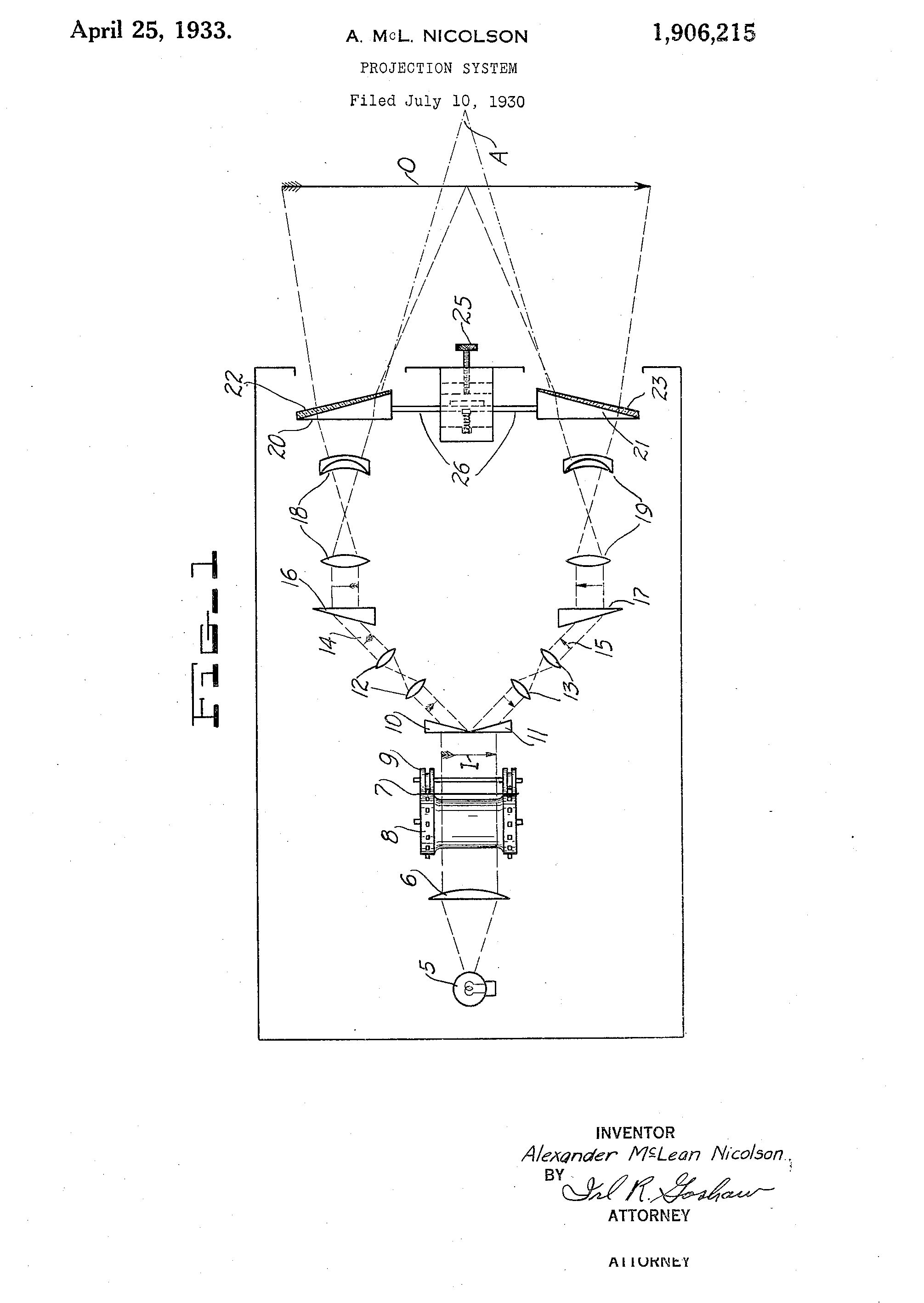
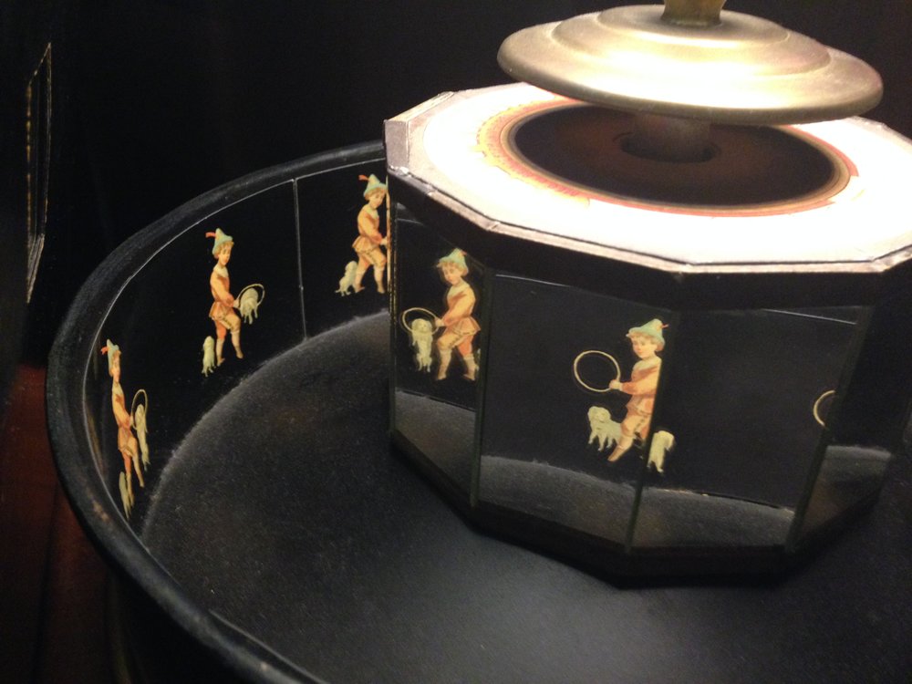
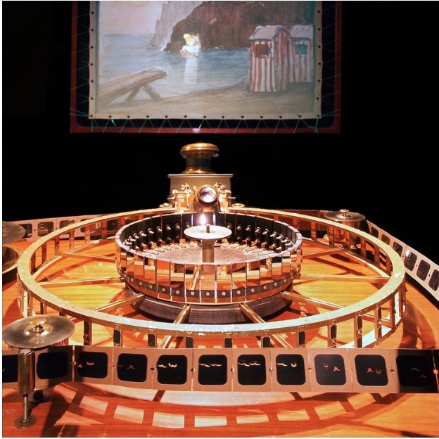 The praxinoscope uses an optical mechanism of a mirrored polygon sitting inside an encircling metal drum twice its diameter. Reynaud described the polygon as a ‘cage of mirrors’, a series of twelve small vertical mirrors glued to each other and positioned in the centre of the drum. The polygon and the drum rotate on the same axis. Each mirrored facet of the polygon reflects a single and different image frame painted on the inside of the drum. Collectively, the images make up a frame-by-frame sequence of movement, so that when the device rotates in front of a viewer, it creates the appearance of a moving image. Reynaud later developed the praxinoscope device into a more elaborate form of the Théâtre Optique, which used hand-painted translucent glass slides on a rotating device allowing up to 250 image frames. He rear-projected these reflected images through an objective lens system onto a screen.
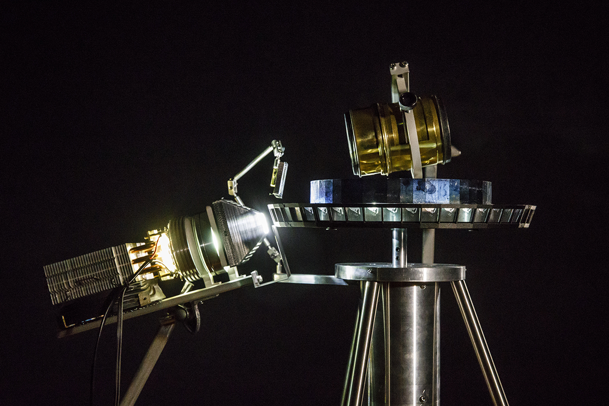 While developing Ghost in the Machine it proved challenging to generate a projected moving image that wasn’t blurred. To overcome this problem I applied Reynaud’s technique of individually reflecting each image frame on to a matching mirrored plane. This concept worked because in contrast to my image frames, where each image presents a different stage of movement, each segment of mirror is identical. It is the image reflected from the mirror (and not the translucent image frame per se) that travels through the objective lens and is projected on to the screen. So while the mirrored plane renders the moving image legible, its reflective properties hide the mirror in plain sight – as the viewer of the projected image, I don’t perceive the changing mirror plane, only the different stages of movement foregrounded on an apparently static background.
Reflective properties of the mirror have become a significant element in my continued exploration of projected moving image systems. Contemplating how the mirrored polygon renders itself invisible through its own materiality, mirror, in addition to glass and light, is a key material for my explorations of wonder and (in)visibility and will be the key material explored during the residency.
Polygon problems, new ideas and the ANAT Synapse Artist Residency
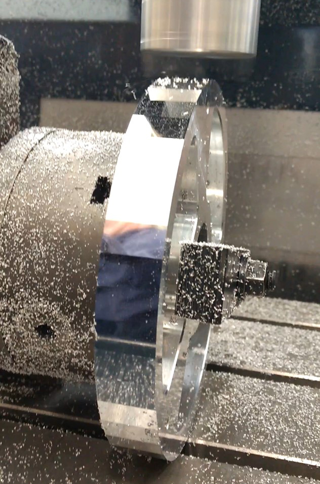 Fabricating the polygon proved to be the most problematic component of Ghost in the Machine, but also one that provided numerous ‘next steps’ in my practice. Machinist engineer Neil Devlin at the RSP who, being the innovative master he is, milled and polished the polygon by fly-cutting the surfaces using a diamond tool from the School’s ultra-precision lathe. The rotating polygon, the process of making it and understanding optical mechanics gave me new ideas for creating moving images in novel ways.
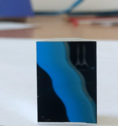
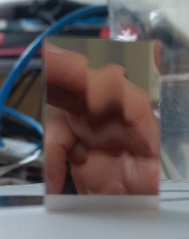
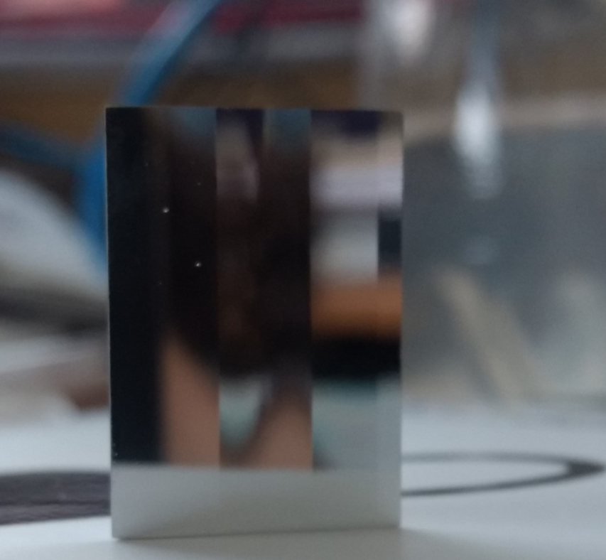
After learning so much from creating Ghost in the Machine, late last year I completed a small pilot study with Geoff at the RSP as part of my ANU Vice Chancellors Creative Research Fellowship. We used the precision lathe to cut and optically polish different mirrored facets to investigate if, instead of using an image carousel with 48 image frames, as in Ghost in the Machine, we could generate a moving image from a single image source. The optical premise was that having multiple reflective planes on a single mirror facet would change the direction of light. Therefore when an image was projected onto the mirrored plane, it could be controlled to bend or change in specific ways to create the illusion of movement.
Our results from this initial study were promising and we now plan to develop this idea further as part of our ANAT Synapse collaboration. Our main fabrication tool will be the ultra-precision lathe as it can achieve extremely high-level and precise polished surfaces. I will also prototype specific components using additional fabrication technologies in the MakerSpace located in the RSP. From precursory conversations between Geoff and myself, this residency will open up many more possibilities, other than mirrored components, within my optical systems. We will also explore different materials and fabrication processes using the lathe (transparent as well as reflective), and iteratively test how these novel components can bring to fruition previously unimagined ways of generating projected moving images. My task will then be to see if these systems evoke an experience of wonder in a contemporary audience.
Stay tuned for additional ‘experiments-in-progress’ blog posts during my residency.
Thank you ANAT for this wonderful opportunity!
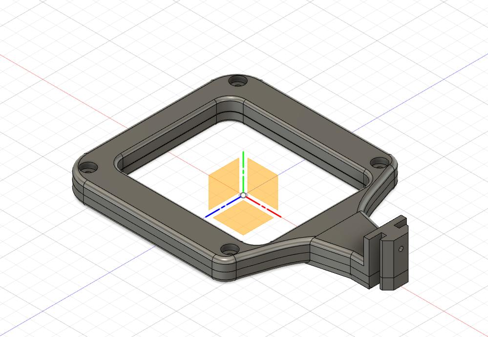
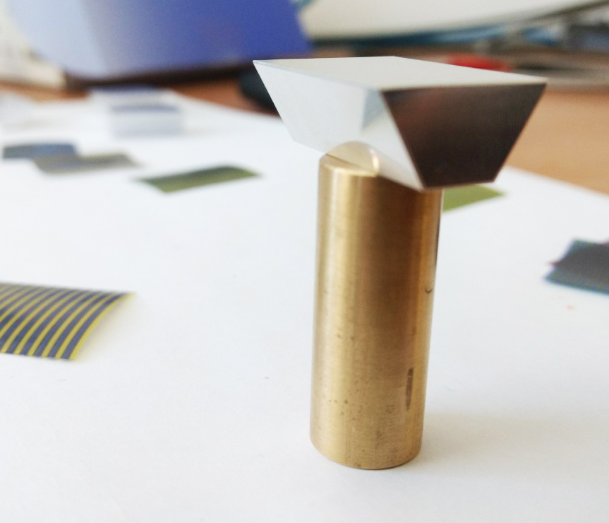
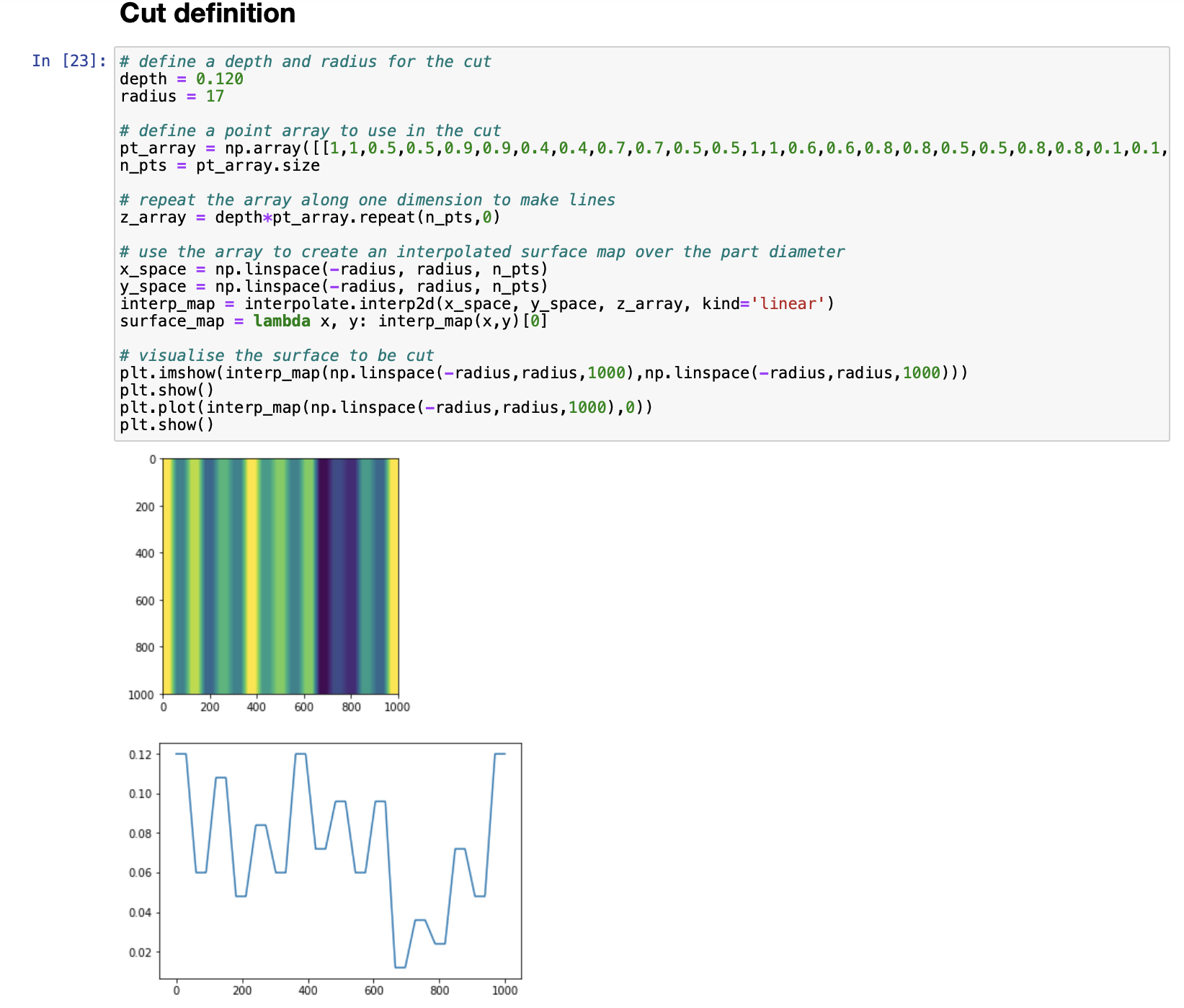
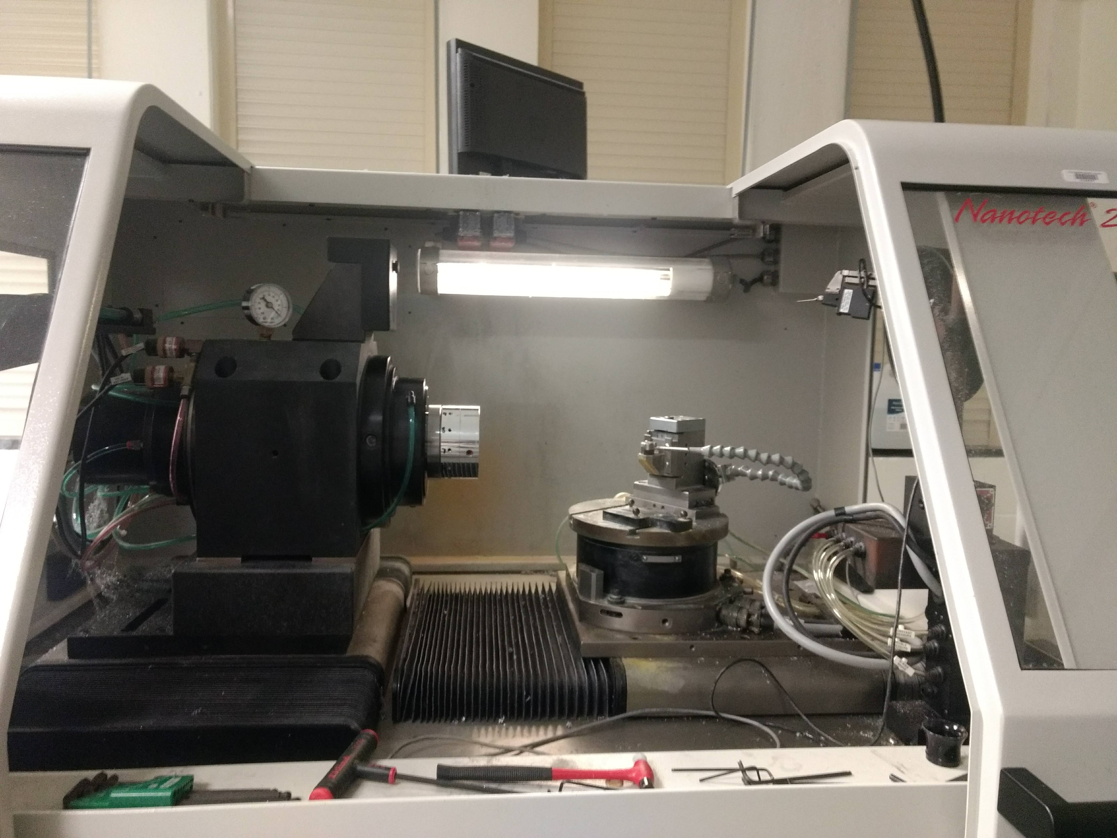
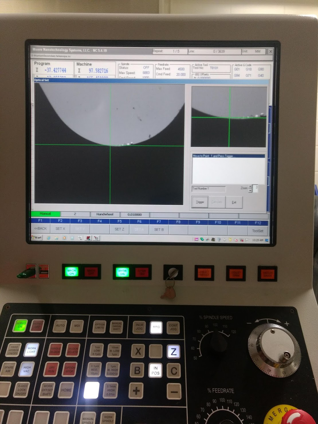
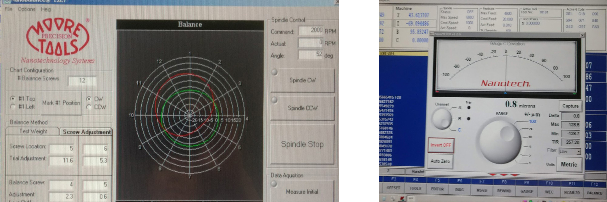
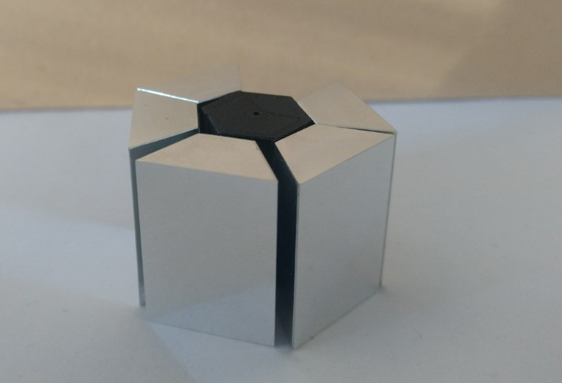
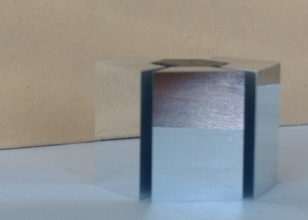
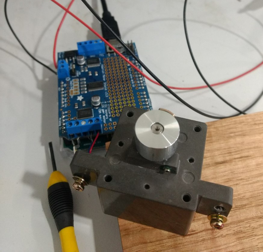
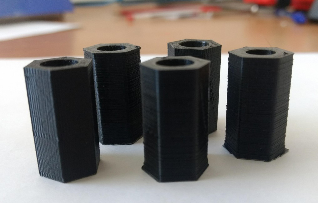
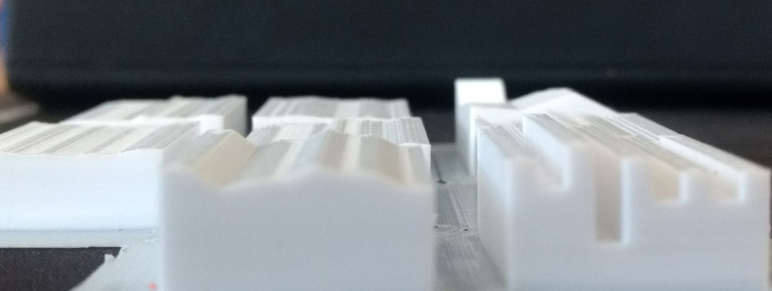 To begin a conversation with Geoff about the mirror cuts, I 3D modelled and printed some surface profiles. Understanding now how the nano-lathe works has modified my thinking about how to make the mirrored facets. Geoff wrote a python script to approximate the spline into a series of points and then turned this into g-code for the nano-lathe. The machine also cuts very slowly, for example a facet of 18mm x 25mm takes about 4 hours to cut about 120 microns (0.12mm).